Magnetic suspension control moment gyroscope high-speed rotor device

A technology for controlling torque gyroscopes and high-speed rotors, which is applied in the directions of space navigation vehicle guidance devices, transportation and packaging, space navigation equipment, etc. and other problems, to meet the needs of aerospace applications, with higher cost and lower power consumption.

Active Publication Date: 2019-11-12
BEIHANG UNIV
View PDF8 Cites 4 Cited by
  • Summary
  • Abstract
  • Description
  • Claims
  • Application Information

AI Technical Summary

Problems solved by technology

The existing magnetic levitation control moment gyro high-speed rotor support system usually adopts radial magnetic bearings arranged in pairs to support the two radial translation and rotation of the rotor, and uses axial magnetic bearings arranged in pairs to support the axial translation of the rotor. The disadvantage of the support method is that the radial magnetic bearing and axial magnetic bearing are arranged along the axial direction of the rotor. The size of the rotor bearing is too large, and the gyro room also needs a larger envelope size, which is not conducive to reducing the weight of the system.
At the same time, the longer axial dimension also restricts the increase of the natural frequency of the rotor during the design process
[0003] Chinese patent ZL200710065550.1 "Completely non-contact single-frame magnetic levitation control moment gyro" uses a rotor system supported by magnetic bearings for the high-speed rotor, which greatly improves the working speed and service life of the gyro rotor. However, the radial magnetic bearings, axial The magnetic bearing and high-speed motor are arranged separately along the axial direction of the rotor, so that the axial length of the rotor assembly is relatively large; The high-speed motor and the axial magnetic bearing in the single-frame control torque gyro with end support" and the Chinese patent CN201810075967 "a low-power consumption control torque gyro high-speed rotor system" are located on the inner and outer circles of the same plane, but the magnetic bearing support system still uses Separate radial magnetic bearing and axial magnetic bearing, it is difficult to further reduce the volume and mass of the rotor system

Method used


Image

  • Magnetic suspension control moment gyroscope high-speed rotor device
  • Magnetic suspension control moment gyroscope high-speed rotor device
  • Magnetic suspension control moment gyroscope high-speed rotor device

Examples


Embodiment Construction

[0020] The present invention will be further described below in conjunction with the accompanying drawings and specific embodiments.

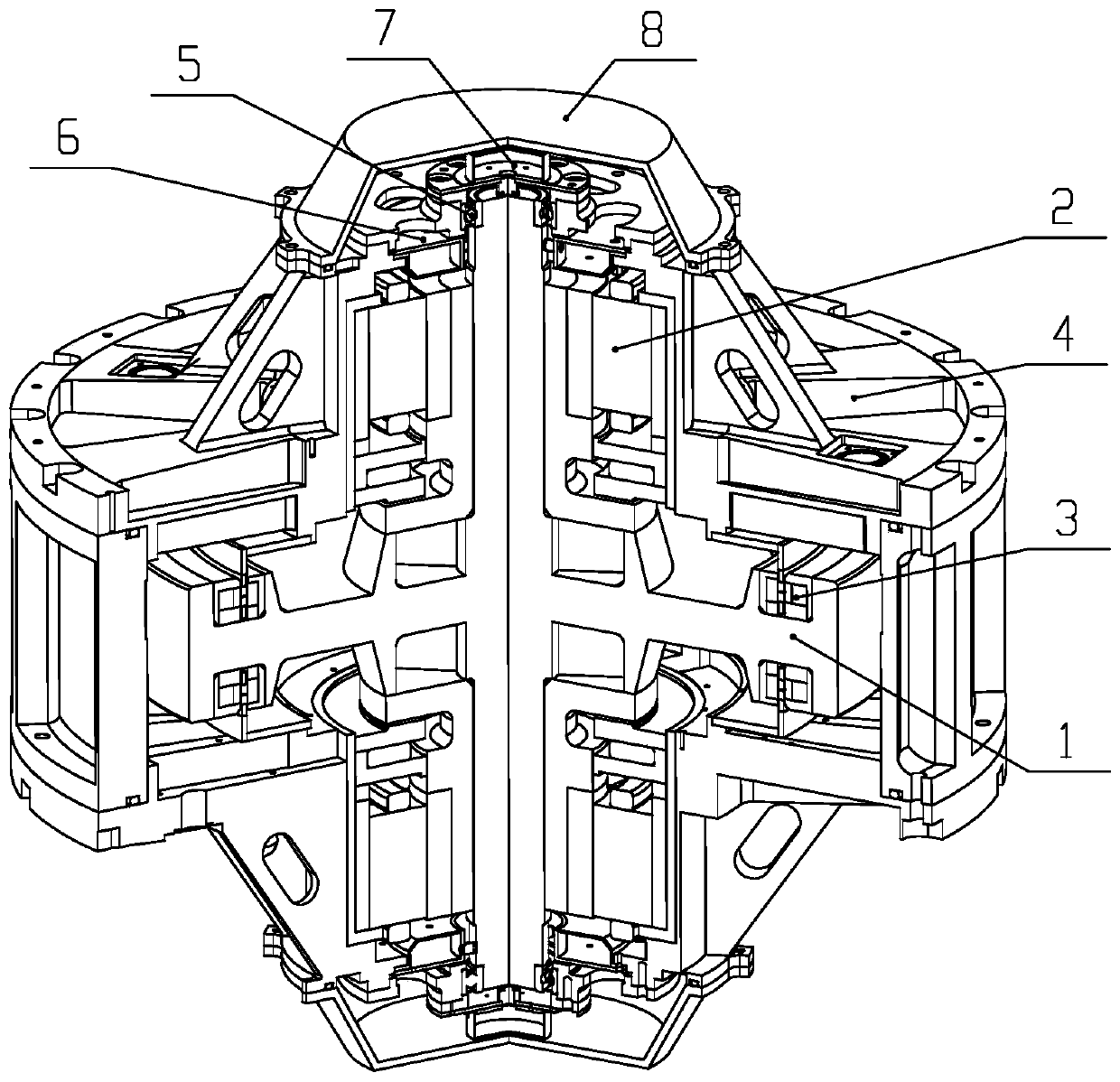
[0021] Such as figure 1 As shown, a magnetic levitation control moment gyro high-speed rotor device is mainly composed of a flywheel 1, a three-degree-of-freedom integrated magnetic bearing 2, a high-speed motor 3, a gyro room 4, a protective bearing 5, a radial displacement sensor 6, and an axial displacement sensor 7 And end cap 8 composition. Among them, the flywheel 1, the rotor part of the high-speed motor 3, the rotor part of the three-degree-of-freedom integrated magnetic bearing 2 constitute the rotor assembly of the device, and the gyro room, the stator part of the high-speed motor, the stator part of the three-degree-of-freedom integrated magnetic bearing and the end cover form the stator assembly. The high-speed motor 3 is used to realize the high-speed rotation of the rotor between the rotor assembly and the stator assembly, and at...


PUM


Abstract

The invention discloses a magnetic suspension control moment gyroscope high-speed rotor device. The device comprises a flywheel, three-degree-of-freedom integrated magnetic bearings, a high-speed motor, a gyroscope case, a protective bearing, a radial displacement sensor, an axial displacement sensor and an end cover, wherein a rotor component of the device is composed of the flywheel, a rotor part of the high-speed motor and rotor parts of the three-degree-of-freedom integrated magnetic bearings, a stator component is composed of the gyroscope case, a stator part of the high-speed motor, stator parts of the three-degree-of-freedom integrated magnetic bearings and the end cover, and high-speed rotation of a rotor is achieved between the rotor component and the stator component through thehigh-speed motor to provide angular momentum for output torque of a gyroscope. According to the device, through supporting by the two three-degree-of-freedom integrated magnetic bearings which are symmetrically arranged, radial and axial non-contact stable suspension of the rotor can be achieved, so that a magnetic bearing supporting system is compact in layout, the size and weight of the device are reduced, the axial length of the rotor can be shortened so that higher rotor inherent frequency and higher rotating speed can be obtained.

Description

technical field [0001] The invention relates to the technical field of torque control gyroscopes, in particular to a high-speed rotor device for magnetic suspension control torque gyroscopes. Background technique [0002] The control moment gyroscope has the characteristics of large output torque and high control precision, and is an ideal actuator for the attitude stability control of large spacecraft and the flexible attitude adjustment of small and medium-sized agile satellites. Due to the non-contact suspension support of the magnetic suspension bearing, it can overcome the friction and wear caused by the mechanical bearing, reduce the vibration and noise of the system, and does not need lubrication. The advantages of high reliability have obvious technical advantages compared with mechanical torque gyroscopes. In order to realize the stable driving of the high-inertia high-speed rotor around the main shaft, it is necessary to provide the rotation degree of freedom in o...

Claims


Application Information

Patent Timeline
Patent Type & Authority Applications(China)
IPC IPC(8): B64G1/28
CPCB64G1/286
Inventor 韩邦成叶向阳郑世强李海涛刘刚
Owner BEIHANG UNIV
Why Eureka
Try Eureka