
Soft X-ray microscopic imaging detector

A microscopic imaging and X-ray technology, which is applied in the use of radiation for material analysis, etc., can solve the problems of chip damage, damage, complicated use, etc., and achieve the effect of improving the conversion quality, not easy to damage, and easy to implement

Pending Publication Date: 2019-11-15
RAYCAN TECH CO LTD SU ZHOU
View PDF0 Cites 1 Cited by
  • Summary
  • Abstract
  • Description
  • Claims
  • Application Information

AI Technical Summary

Problems solved by technology

[0006] There are still many problems in traditional soft X-ray detectors. For example, traditional soft X-ray imaging equipment uses laser plasma as a light source. Radiation interference, these visible light, ultraviolet rays and X-rays are difficult to remove by conventional optical path design, which will have a great impact on imaging; at the same time, due to the weak light source intensity of soft X-ray microscopic imaging instruments, traditional CCD detectors can pass through for a long time Exposure to obtain imaging pictures, the soft X-ray generated by laser plasma is a periodic pulse with a short duration. During this exposure time, the effective duration of soft X-ray accounts for a small proportion, resulting in a large number of Accumulation of noise, reducing the imaging signal-to-noise ratio
Secondly, the traditional soft X-ray detector uses a direct detection CCD for detection. The CCD chip is exposed and easily stained by dust, splashes, etc., causing damage; therefore, an additional filter is required. Composed of thin metal film, using metal mesh as support, it is easy to damage
Again, traditional soft X-ray imaging detectors cannot avoid direct radiation of high-energy X-rays on the CCD chip, which will not only generate noise interference, but also damage the chip after long-term use
In addition, the equipment also needs to be equipped with additional optical devices such as apertures and shading tubes, which are very complicated to use and cannot avoid light leakage.

Method used


Image

  • Soft X-ray microscopic imaging detector
  • Soft X-ray microscopic imaging detector
  • Soft X-ray microscopic imaging detector

Examples


Embodiment Construction

[0032] The present invention will be further described below in conjunction with specific embodiments. It should be understood that the following examples are only used to illustrate the present invention but not to limit the scope of the present invention.

[0033] It should be noted that when a component / feature is referred to as being “disposed on” another component / part, it can be directly disposed on the other component / part or an intervening component / part may also be present. When a component / part is referred to as being "connected / coupled" to another component / part, it can be directly connected / coupled to the other component / part or intervening parts / parts may also be present. As used herein, the term "connected / coupled" may include electrical and / or mechanical physical connections / coupled. As used herein, the term "comprising / comprising" refers to the presence of a feature, step or component / part, but does not exclude the presence or addition of one or more other fea...


PUM

PropertyMeasurementUnit
thicknessaaaaaaaaaa
thicknessaaaaaaaaaa
reflectanceaaaaaaaaaa

Abstract

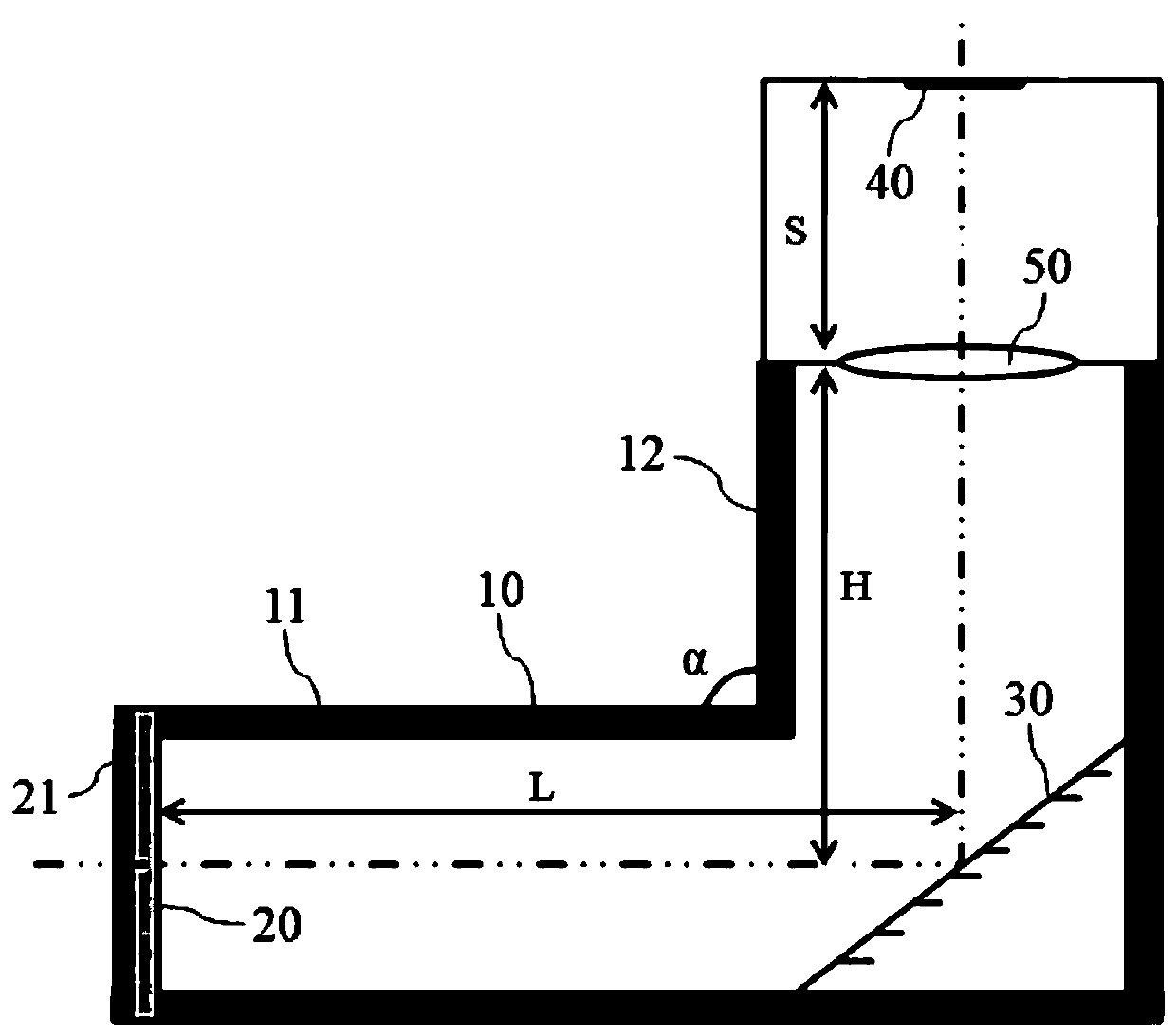
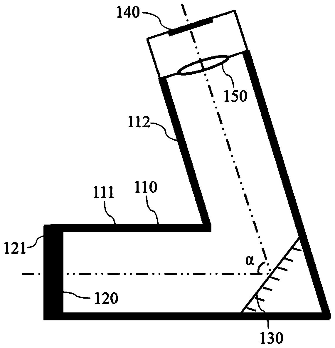
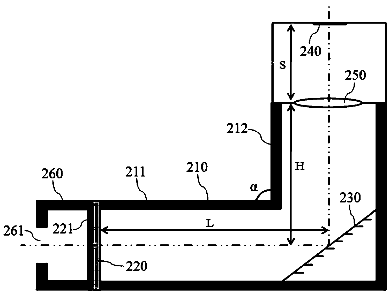
The invention discloses a soft X-ray microscopic imaging detector comprising a cavity, a fluorescence conversion screen and a photoelectric conversion device, wherein the cavity comprises a first opening and a second opening, the cavity is internally arranged with a reflective device that reflects the light incident from the first opening to the second opening, and a first angle is defined betweenthe direction in which the light propagates from the first opening toward the reflective device and the direction in which the light propagates from the reflective device toward the second opening; the fluorescence conversion screen is disposed at the first opening; the photoelectric conversion device is disposed at the second opening; and the photoelectric conversion device, the fluorescence conversion screen and the cavity forms a closed space. The soft X-ray microscopic imaging detector provided by the invention avoids direct radiation of soft X-rays onto the photoelectric conversion device, improves the detection effect, prolongs the service life of the photoelectric conversion device, and is simple in structure and easy to implement.

Description

technical field [0001] The invention relates to the technical field of microscopic imaging, in particular to a soft X-ray microscopic imaging detector. Background technique [0002] Traditional optical microscopy imaging technology uses visible light (wavelength range 390nm-700nm) for imaging. Due to the limitation of diffraction limit, it is difficult to achieve a resolution below 200nm. Electron microscope imaging technology uses electrons for imaging. Although the resolution is improved, due to the weak penetrating ability of electrons, it cannot penetrate cells to perform three-dimensional imaging of the inside of cells; at the same time, electron microscope imaging requires biological samples such as slicing, dehydration, etc. processing, which undoubtedly destroys the internal structural information of the sample, making it impossible to image intact aqueous cells. [0003] X-rays have high penetrating power and can pass through many substances that are opaque to visi...

Claims


Application Information

Patent Timeline
Patent Type & Authority Applications(China)
IPC IPC(8): G01N23/04
CPCG01N23/04
Inventor 郑睿肖鹏谢庆国钟胜王卫东唐江褚倩白翔
Owner RAYCAN TECH CO LTD SU ZHOU
Learn More