Photoemission electron microscopy imaging method and imaging system capable of working under atmospheric conditions close to normal pressure

A technology of emitting electrons and microscopic imaging, which is applied in the direction of electrical components, circuits, discharge tubes, etc.

Active Publication Date: 2020-05-05
DALIAN INST OF CHEM PHYSICS CHINESE ACAD OF SCI
View PDF5 Cites 0 Cited by
  • Summary
  • Abstract
  • Description
  • Claims
  • Application Information

AI Technical Summary

Problems solved by technology

It is still a huge challenge to directly apply PEEM technology to surface research under normal or near normal pressure conditions, and this aspect has not been reported yet

Method used


Image

  • Photoemission electron microscopy imaging method and imaging system capable of working under atmospheric conditions close to normal pressure
  • Photoemission electron microscopy imaging method and imaging system capable of working under atmospheric conditions close to normal pressure
  • Photoemission electron microscopy imaging method and imaging system capable of working under atmospheric conditions close to normal pressure

Examples


Embodiment 1

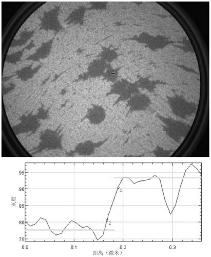
[0044] PEEM imaging under ultra-high vacuum conditions ( image 3 ). The sealed atmosphere chamber is a vacuum environment, the potential difference between the sample and the conical tube is 5kV, and the potential difference between the conical tube and the objective lens is 10kV. The sample is a single-layer graphene structure grown on the surface of a Ru(0001) single crystal. Hg lamp light source is used, the image size is 14 microns, the photoelectron signal on the surface of Ru substrate is weak, which appears as a dark area, and the graphene structure shows a higher gray scale. image 3 The lower curve corresponds to the gray level distribution of the black line area in the figure, and the resulting spatial resolution is about 20nm (the distance between points 1 and 2 in the curve). This case illustrates that the NAP-PEEM device of the present invention can achieve a spatial resolution comparable to conventional PEEM under ultra-high vacuum conditions.

Embodiment 2

[0046] PEEM imaging of the intermediate state ( Figure 4 ). The nitrogen pressure in the sealed atmosphere chamber is 0.12mbar, and after the gas differential pumping, the pressure of the PEEM imaging chamber is 1.2×10 -6 mbar, the pressure at the detector is 1.2×10 -8 mbar. The potential difference between the sample and the conical tube is 5kV, the potential difference between the conical tube and the objective lens is 10kV, and the sample is a single-layer graphene structure grown on the Ru(0001) single crystal surface. Figure 4 The lower curve corresponds to the gray level distribution of the black line area in the figure, and the resulting spatial resolution is about 25nm. This case illustrates that the NAP-PEEM device of the present invention can achieve higher spatial resolution under an atmosphere of 0.12 mbar.

Embodiment 3

[0048] PEEM imaging in a near-atmospheric atmosphere ( Figure 5 ). The nitrogen pressure in the sealed atmosphere chamber is 1.2mbar, and after the gas differential pumping, the pressure of the PEEM imaging chamber is 1.2×10 -5 mbar, the pressure at the detector is 1.2×10 -7 mbar. The potential difference between the sample and the conical tube is 0.3kV, and the potential difference between the conical tube and the objective lens is 5.7kV. The sample is a single-layer graphene structure grown on the Ru(0001) single crystal surface. Figure 5 The lower curve corresponds to the gray level distribution of the black line area in the figure, and the resulting spatial resolution is about 100nm. This case shows that the NAP-PEEM device in the present invention can realize PEEM imaging in a near-atmospheric pressure atmosphere of 1.2 mbar, reaching a spatial resolution of 100 nm.


PUM


Abstract

The invention relates to a light-emitting electron microscopic imaging method capable of working under approximate atmospheric pressure conditions. The method is capable of effectively loading a highelectric field while maintaining high atmospheric pressure. The method is applied to a light-emitting electron microscope (PEEM) system to realize PEEM imaging under approximate atmospheric pressure conditions. PEEM imaging under approximate atmospheric pressure conditions is achieved through fractional electron-accelerated electronic optical path system and a gas pressure differential pumping system. Spatial resolution of 100 nm is achieved. A hollow conical tube added between a sample and an objective lens is both the application position of the primary voltage and the first-order differential pumping of the gas pressure. A designed atmosphere chamber has the functions of light source introduction, gas introduction / evacuation and chamber sealing, so that an approximate atmospheric pressure environment is between the top of the conical tube and a sample. In-situ and dynamic surface imaging studies of a surface nanostructure under approximate real working conditions are achieved by coupling the atmosphere chamber and a conventional PEEM imaging component.

Description

technical field [0001] The present invention relates to a new technology and new method of surface scientific research, specifically, a vacuum system and a gas control system with multi-stage differential pumping functions have been developed, and an electronic optical path system with graded electron acceleration is realized to work under atmospheric conditions close to normal pressure. The function of NAP-PEEM can conduct in-situ and dynamic surface imaging research on surface nanostructures, and observe the surface dynamic process in nanosystems under high spatial resolution conditions, which can be applied to catalytic chemistry and surface physics. , thin film growth and other surface science research fields. Background technique [0002] Photoemission Electron Microscopy (PEEM) uses the principle of photoelectric effect to excite electrons in solid surface atoms with ultraviolet light or X-ray light, and uses advanced electron optical system to focus and amplify the su...

Claims


Application Information

Patent Timeline
Patent Type & Authority Patents(China)
IPC IPC(8): H01J37/26H01J37/16
CPCH01J37/16H01J37/26H01J37/265
Inventor 傅强宁艳晓包信和
Owner DALIAN INST OF CHEM PHYSICS CHINESE ACAD OF SCI
Why Eureka
Try Eureka