An imaging system and method combining a tunable deep ultraviolet laser source with a near-atmospheric pressure light emission electron microscope

An electron microscope and imaging system technology, applied in the field of surface scientific research, can solve the problems of limited synchrotron radiation light source resources and limit the wide application of PEEM, and achieve the effect of improving spatial resolution and application fields

Active Publication Date: 2020-05-05
DALIAN INST OF CHEM PHYSICS CHINESE ACAD OF SCI
View PDF6 Cites 0 Cited by
  • Summary
  • Abstract
  • Description
  • Claims
  • Application Information

AI Technical Summary

Problems solved by technology

However, due to the limited resources of synchrotron radiation sources, using it as an excitation source will greatly limit the wide application of PEEM.

Method used


Image

  • An imaging system and method combining a tunable deep ultraviolet laser source with a near-atmospheric pressure light emission electron microscope
  • An imaging system and method combining a tunable deep ultraviolet laser source with a near-atmospheric pressure light emission electron microscope
  • An imaging system and method combining a tunable deep ultraviolet laser source with a near-atmospheric pressure light emission electron microscope

Examples


Embodiment 1

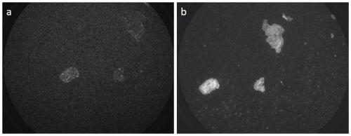
[0056] The graphene structures prepared on the surface of Nb-doped STO were respectively illuminated by Hg light source ( image 3 a) and deep ultraviolet light source (210nm) ( image 3 b) PEEM imaging under ultra-high vacuum conditions for the excitation light source. The atmosphere chamber is a vacuum environment, the potential difference between the sample and the conical tube is 5kV, and the potential difference between the conical tube and the objective lens is 10kV. The image size is 50 microns, the work function of STO is relatively high, the surface photoelectron signal is weak, which appears as dark areas, and the graphene structure shows high gray scale. Excite the surface with a deep ultraviolet laser because of its high energy, image 3 b shows higher graphene brightness and higher structural resolution. This case shows that deep ultraviolet laser has improved the application field of PEEM.

Embodiment 2

[0058] Single-layer graphene structure grown on Ru(0001) single crystal surface, PEEM imaging of the intermediate state with Hg lamp as excitation light source ( Figure 4 ). The nitrogen pressure in the atmosphere chamber is 0.12mbar, and after the gas differential pumping, the pressure of the PEEM imaging chamber is 1.2×10 -6 mbar, the pressure at the detector is 1.2×10 -8 mbar. The potential difference between the sample and the conical tube is 5kV, and the potential difference between the conical tube and the objective lens is 10kV. With an image size of 14 μm, the photoelectron signal on the Ru substrate surface is weak, appearing as dark areas. Figure 4 The lower curve corresponds to the gray distribution of the yellow line area in the picture, and the resulting spatial resolution is about 25nm. This case illustrates that the near-atmospheric pressure PEEM device in the present invention can achieve higher spatial resolution in an atmosphere of 0.12 mbar.

Embodiment 3

[0060] The single-layer graphene structure grown on the Ru(0001) single crystal surface was imaged by PEEM under near-atmospheric pressure using a Hg lamp as the excitation light source ( Figure 5 ). The nitrogen pressure in the atmosphere chamber is 1.2mbar. After the gas differential pumping, the pressure of the PEEM imaging chamber is 1.2×10 -5 mbar, the pressure at the detector is 1.2×10 -7 mbar. The potential difference between the sample and the conical tube is 0.3kV, and the potential difference between the conical tube and the objective lens is 5.7kV. Figure 5The lower curve corresponds to the gray level distribution of the yellow line area in the picture, and the resulting spatial resolution is about 100nm. This case shows that the near-atmospheric pressure PEEM device in the present invention can realize PEEM imaging in a near-atmospheric pressure atmosphere of 1.2 mbar, reaching a spatial resolution of 100 nm.


PUM


Abstract

The invention relates to a method capable of effectively loading a high electric field while maintaining high atmospheric pressure. The method is applied to a light-emitting electron microscope (PEEM)system to realize PEEM imaging under a condition close to normal atmospheric pressure. At the same time, a tunable deep ultraviolet laser source is used as an excitation light source, which improvesthe spatial resolution and application field of PEEM. Through an electronic optical path system of graded electron acceleration and a differential pumping system of gas pressure, PEEM imaging under anear atmospheric pressure atmosphere can be realized, and spatial resolution of 100nm is realized. A conical tube is added between a sample and an objective lens, the conical tube is not only a placewhere first-level voltage is applied, but also realizes first-level differential pumping of gas pressure. A designed atmosphere chamber has the functions of light source introduction, gas introduction / evacuation, chamber sealing and the like, and a near atmospheric pressure environment is between the conical tube and the sample. By combining the atmosphere chamber with a traditional PEEM device and the tunable deep ultraviolet laser source, in-situ, dynamic surface imaging research of surface nanostructures under near-real working conditions is achieved.

Description

technical field [0001] The present invention relates to a new technology and new method of surface scientific research, specifically, a vacuum system and a gas control system with multi-stage differential pumping functions have been developed, and an electronic optical path system with graded electron acceleration is realized to work under atmospheric conditions close to normal pressure. The NAP-PEEM function; using a tunable deep ultraviolet laser source as the excitation light source, using the characteristics of high energy, high intensity and adjustable wavelength of the laser to improve the spatial resolution of NAP-PEEM and expand its application field; the combination of the two can conduct in-situ and dynamic surface imaging research on a variety of surface nanostructures, which can be applied in catalysis, energy, nanoscience, biology, microelectronics, materials and other fields. Background technique [0002] Photoemission Electron Microscopy (PEEM) uses the princi...

Claims


Application Information

Patent Timeline
Patent Type & Authority Patents(China)
IPC IPC(8): H01J37/075H01J37/26
CPCH01J37/075H01J37/26
Inventor 宁艳晓傅强包信和
Owner DALIAN INST OF CHEM PHYSICS CHINESE ACAD OF SCI
Why Eureka
Try Eureka