Light-emitting electron microscopic imaging method capable of working under approximate atmospheric pressure conditions and imaging system thereof
A technology for emitting electrons and microscopic imaging, which is used in electrical components, circuits, discharge tubes, etc.
- Summary
- Abstract
- Description
- Claims
- Application Information
AI Technical Summary
Problems solved by technology
Method used
Image
Examples
Embodiment 1
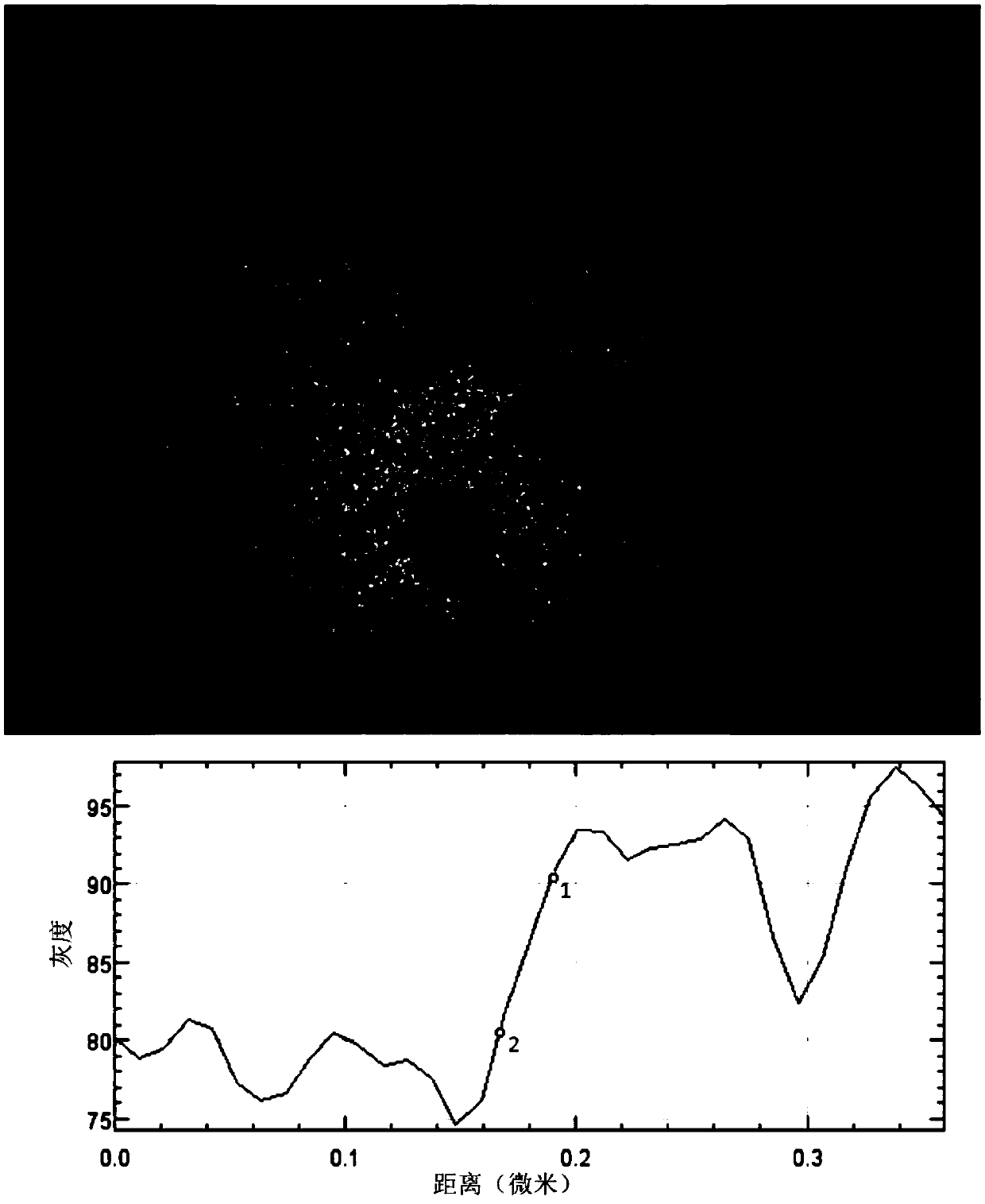
[0044] PEEM imaging under ultra-high vacuum conditions ( image 3 ). The sealed atmosphere chamber is a vacuum environment, the potential difference between the sample and the conical tube is 5kV, and the potential difference between the conical tube and the objective lens is 10kV. The sample is a single-layer graphene structure grown on the surface of a Ru(0001) single crystal. Hg lamp light source is used, the image size is 14 microns, the photoelectron signal on the surface of Ru substrate is weak, which appears as a dark area, and the graphene structure shows a higher gray scale. image 3 The lower curve corresponds to the gray level distribution of the black line area in the figure, and the resulting spatial resolution is about 20nm (the distance between points 1 and 2 in the curve). This case illustrates that the NAP-PEEM device of the present invention can achieve a spatial resolution comparable to conventional PEEM under ultra-high vacuum conditions.
Embodiment 2
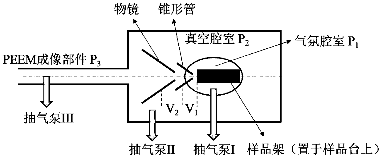
[0046] PEEM imaging of the intermediate state ( Figure 4 ). The nitrogen pressure in the sealed atmosphere chamber is 0.12mbar, and after the gas differential pumping, the pressure of the PEEM imaging chamber is 1.2×10 -6 mbar, the pressure at the detector is 1.2×10 -8 mbar. The potential difference between the sample and the conical tube is 5kV, the potential difference between the conical tube and the objective lens is 10kV, and the sample is a single-layer graphene structure grown on the Ru(0001) single crystal surface. Figure 4 The lower curve corresponds to the gray level distribution of the black line area in the figure, and the resulting spatial resolution is about 25nm. This case illustrates that the NAP-PEEM device of the present invention can achieve higher spatial resolution under an atmosphere of 0.12 mbar.
Embodiment 3
[0048] PEEM imaging in a near-atmospheric atmosphere ( Figure 5 ). The nitrogen pressure in the sealed atmosphere chamber is 1.2mbar, and after the gas differential pumping, the pressure of the PEEM imaging chamber is 1.2×10 -5 mbar, the pressure at the detector is 1.2×10 -7 mbar. The potential difference between the sample and the conical tube is 0.3kV, and the potential difference between the conical tube and the objective lens is 5.7kV. The sample is a single-layer graphene structure grown on the Ru(0001) single crystal surface. Figure 5 The lower curve corresponds to the gray level distribution of the black line area in the figure, and the resulting spatial resolution is about 100nm. This case shows that the NAP-PEEM device in the present invention can realize PEEM imaging in a near-atmospheric pressure atmosphere of 1.2 mbar, reaching a spatial resolution of 100 nm.
PUM
 Abstract
Description
Claims
Application Information
 - R&D
- Intellectual Property
- Life Sciences
- Materials
- Tech Scout
- Unparalleled Data Quality
- Higher Quality Content
- 60% Fewer Hallucinations
Browse by: Latest US Patents, China's latest patents, Technical Efficacy Thesaurus, Application Domain, Technology Topic, Popular Technical Reports.
© 2025 PatSnap. All rights reserved.Legal|Privacy policy|Modern Slavery Act Transparency Statement|Sitemap|About US| Contact US: help@patsnap.com


