Distributed water feeding type multistage-AO series-connection efficient biological denitrification system and method

A technology for biological denitrification and water inflow, which is applied in the fields of water pollutants, sustainable biological treatment, chemical instruments and methods, etc., can solve the problems of high energy consumption for denitrification and low denitrification rate, and achieves low energy consumption and energy saving. Power and equipment, the effect of improving the total nitrogen removal rate

Active Publication Date: 2019-11-22
ANHUI UNIVERSITY OF ARCHITECTURE
View PDF2 Cites 6 Cited by
  • Summary
  • Abstract
  • Description
  • Claims
  • Application Information

AI Technical Summary

Problems solved by technology

[0005] In order to solve the problems of the prior art, the present invention provides a system and method for distributed water inflow multi-stage AO series high-effi

Method used


Image

  • Distributed water feeding type multistage-AO series-connection efficient biological denitrification system and method
  • Distributed water feeding type multistage-AO series-connection efficient biological denitrification system and method

Examples


Embodiment 1

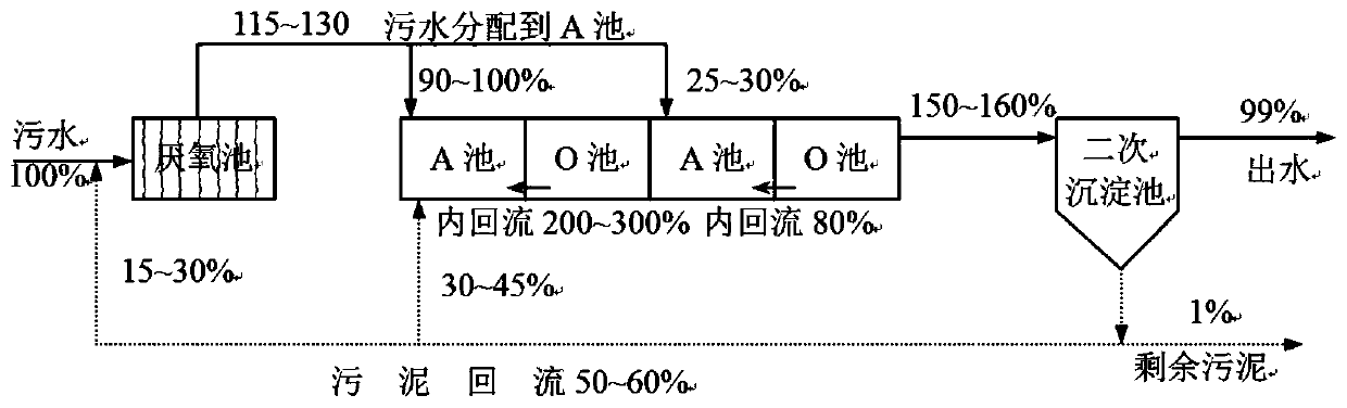
[0040] Embodiment 1 (two-stage AO series process)

[0041] This embodiment provides a process flow in the case of two-stage AO series connection, specifically including:

[0042] Raw sewage first enters the first-stage anoxic pool, which receives the returning sludge at the same time. The function of the first-stage anoxic pool is denitrification and denitrification. At the junction of this pond and the first-stage aerobic pond, an air-lift internal backflow measure is provided, and the nitrifying liquid of the first-stage aerobic pond is returned to the first-stage anoxic pond at a flow rate of about 300% (specifically, the backflow The ratio should be determined according to the water quality). The nitrate in the first-stage anoxic pool comes from the above-mentioned returning sludge and the returning nitrification liquid, and the organic matter in the first-stage anoxic pool comes from raw sewage, so denitrification and denitrification are mainly carried out in the first-s...

Embodiment 2

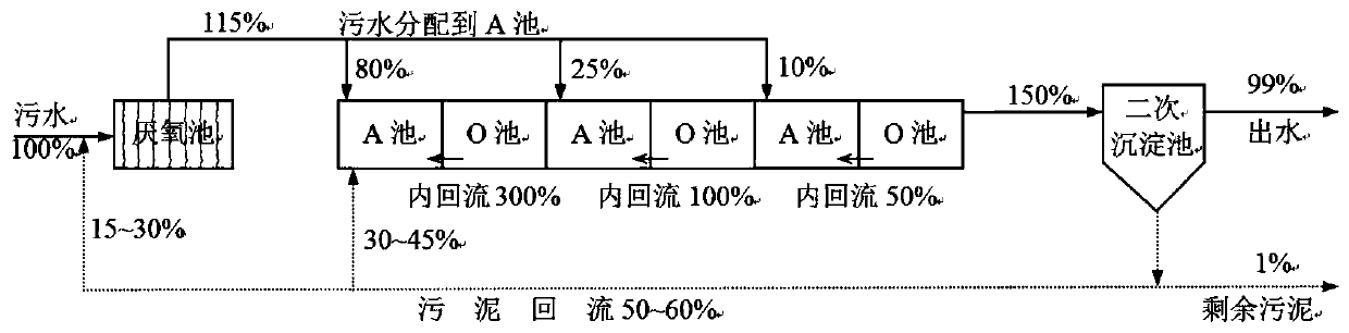
[0046] Embodiment 2 (three-stage AO series process)

[0047] Compared with the two-stage AO process in Example 1, the three-stage AO series process adds an anoxic pool and an aerobic pool. The first four reaction pools have the same functions, and the difference lies in the inflow of sewage flow.

[0048] After being treated in the second-stage aerobic pool, the sewage further enters the third-stage anoxic pool. For the same reason, the third level of anoxic needs to introduce a small amount of raw sewage to supplement the carbon source required for denitrification. On the premise of introducing raw sewage organic matter, the third-stage anoxic tank denitrifies and removes the nitrate from the second-stage aerobic tank and the returned nitrate.

[0049] The sewage further enters the third-level aerobic pool. In the third-level aerobic pool, the ammonia nitrogen (maybe Kjeldahl nitrogen) introduced into the sewage by the third-level anoxic pool is oxidized to nitrate, and fina...


PUM


Abstract

The invention discloses a distributed water feeding type multistage-AO series-connection efficient biological denitrification system and method. According to the method, an anoxic reaction tank and anaerobic reaction tank are used as one stage, two stages or three stages are connected in series in total, nitrification liquid flows back to the anoxic tank of each stage from the aerobic tank of thecorresponding stage in an airlift mode, the backflow ratios of the stages decrease stage by stage, raw sewage flows into the anoxic tanks of the stages in a distributed manner, and the distributed flow also decreases stage by stage. Compared with an existing AN/O denitrification process, the method provided by the invention has the advantages of simpler process flow, lower energy consumption andhigher total nitrogen removal rate, and is suitable for treating sewage with sufficient carbon sources and occasions with higher requirements on the total nitrogen removal rate.

Description

technical field [0001] The invention belongs to the technical field of water environment protection, is an improvement of a traditional biological denitrification process, and specifically relates to a system and method for distributed influent multi-stage AO series high-efficiency biological denitrification. Background technique [0002] In the process of urban sewage treatment, it is generally necessary to remove the main pollution indicators such as organic matter, SS and nitrogen and phosphorus. Since the realization of nitrogen and phosphorus removal is the main goal of the current urban sewage treatment plant, the oxidation ditch, SBR and A 2 / O and other processes with good nitrogen and phosphorus removal functions are the most widely used. Although these processes have higher BOD 5 However, under the condition of limited carbon source, the low removal rate of total nitrogen is a common problem faced by urban sewage treatment plants. In addition, urban sewage plant...

Claims


Application Information

Patent Timeline
IPC IPC(8): C02F3/30C02F3/12C02F101/38
CPCC02F3/121C02F3/308C02F2101/38C02F2209/04C02F2209/16C02F2209/22C02F2301/043C02F2301/08C02F2305/06Y02W10/10
Inventor 唐玉朝唐润朴潘法康伍昌年黄显怀李卫华
Owner ANHUI UNIVERSITY OF ARCHITECTURE
Why Eureka
Try Eureka