Wind power blade deicing device and deicing method

A technology for wind power blades and blades, which is applied in the field of wind power blade deicing devices, and can solve problems such as the inability to guarantee the effectiveness of resistance wires, the difficulty and cost of blade manufacturing processes, and the stress concentration of wind power blades.

Active Publication Date: 2020-07-31
国网山东省电力公司宁津县供电公司
View PDF6 Cites 0 Cited by
  • Summary
  • Abstract
  • Description
  • Claims
  • Application Information

AI Technical Summary

Problems solved by technology

However, the way of the cavity will not only cause the stress concentration of the wind power blades, but also cause the ice layer on some parts of the blade to be unable to be effectively removed due to the incomplete coverage of the cavity; the way of setting the resistance wire inside the blade is not only The process increases the difficulty and cost, and the effectiveness of the resistance wire cannot be guaranteed. At the same time, due to the incomplete layout method, the ice layer on some parts of the blade cannot be effectively removed; and the way of setting the resistance wire outside the blade, the resistance wire is very Vulnerable to damage, effectiveness cannot be guaranteed
There are also some studies to apply anti-icing coatings to the outer surface of the blades, but because the outer surfaces of wind turbine blades have been eroded by wind and sand for a long time, the coatings are very vulnerable to damage, and the composition of the coatings is relatively high.

Method used


Image

  • Wind power blade deicing device and deicing method
  • Wind power blade deicing device and deicing method

Examples


Embodiment 1

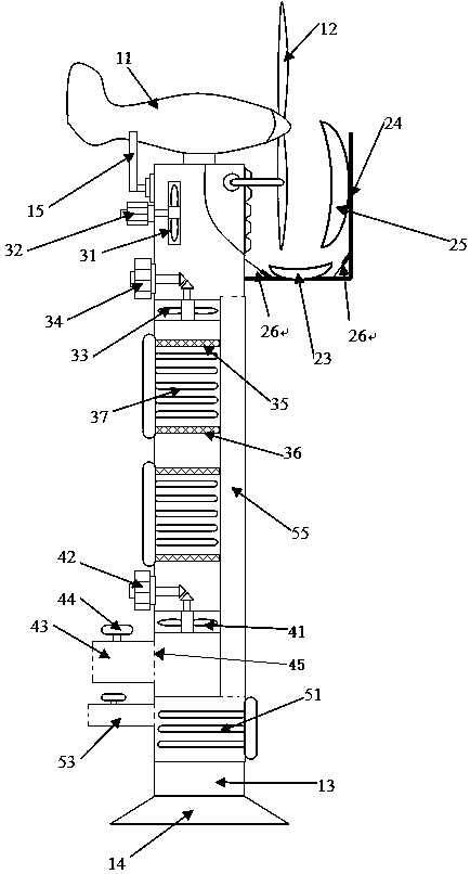
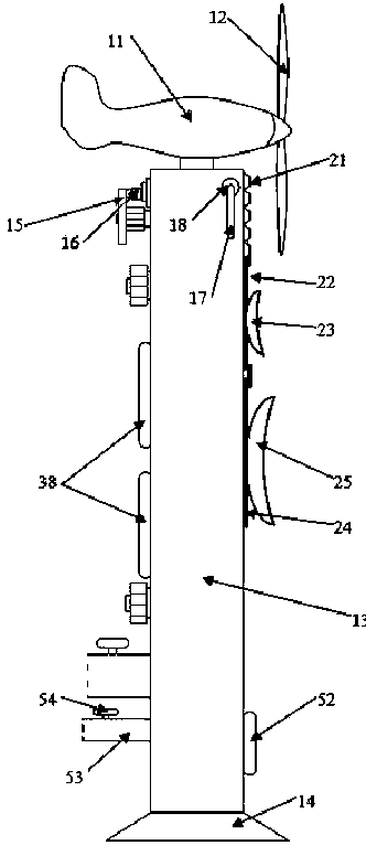
[0031] Further explanation in conjunction with accompanying drawings: as figure 1 and figure 2 The wind power blade deicing device shown includes a wind generator component, a thermal insulation control component, a hot air blowing component and a water vapor processing component. Such as figure 2 As shown, the wind turbine components include a nacelle, a wind power blade, a tower and a base, the nacelle is arranged at the top of the tower and connected to the wind power blade, and the base is arranged at the bottom of the tower for vertically fixing the tower on the ground Above, the interior of the tower is hollow.

[0032] Such as figure 1 and figure 2 As shown, the heat preservation control part includes a cabin fixing rod, a cabin fixing shaft, a blade fixing rod, a blade fixing shaft, a first rotating plate, a first concave mirror, a second rotating plate, a second concave mirror and a rotating plate telescopic rod; The fixed shaft of the nacelle is arranged on t...

Embodiment 2

[0039] The method for deicing wind turbine blades using the wind turbine blade deicing device of Embodiment 1 specifically includes the following steps:

[0040] (1) It is observed that there is icing on the outer surface of the wind turbine blades, inject a mixed liquid of pure water and ethanol through the water inlet pipe, in which the volume ratio of pure water and ethanol is 35:1, and start the water body heater, and use the water body heating rod to The mixed liquid is heated to evaporate it.

[0041] (2) Start one of the engine room fixing shafts to rotate and drive the engine room fixing rod to rotate from the head down to the head up ( figure 1 Due to the occlusion, only one of them can be displayed. In fact, when the head is turned upward, it is impossible to achieve vertical upward, because after contacting the cabin, the cabin fixing rod is inclined, and there is a certain gap between the two cabin fixing rods. angle), fix the position of the nacelle from the side...


PUM


Abstract

The invention belongs to the field of wind power generation treatment and particularly relates to a wind power blade deicing device and a method performing deicing through the device. The device comprises a wind power generator part, a heat preserving control part, a hot air spraying and blowing part and a water vapor treatment part. Due to the fact that the various parts are specifically limited,the purpose that in a local heat preserving area, hot air rich in water vapor and ethyl alcohol steam is sprayed and blown on a wind power blade for deicing is achieved, and a relatively low cost anda good deicing effect are achieved.

Description

technical field [0001] The invention belongs to the field of clean energy, in particular to the field of wind power generation devices and processing methods, in particular to a wind power blade deicing device and a deicing method. Background technique [0002] The hazard of icing on the blades of wind power generation has become a very important negative factor that affects the power generation efficiency of wind turbines and the life of wind turbines. At present, researchers mainly use thermal ablation to melt and remove the ice layer on the outer surface of wind power blades, and this thermal ablation mainly includes the method of setting the cavity inside to feed the hot solution, the method of laying resistance wires inside the blade, and the The way of laying resistance wire externally. However, the way of the cavity will not only cause the stress concentration of the wind power blades, but also cause the ice layer on some parts of the blade to be unable to be effecti...

Claims


Application Information

Patent Timeline
Patent Type & Authority Patents(China)
IPC IPC(8): F03D80/40F03D80/60
CPCF03D80/40F03D80/60Y02E10/72
Inventor 仝伟张若辉李艳娜李昊康忠杰李宗新李海猛王旭
Owner 国网山东省电力公司宁津县供电公司
Why Eureka
Try Eureka