Ceramic ball sphere surface defect detection system

A detection system and surface defect technology, applied in the field of non-contact ceramic sphere surface defect detection system, can solve the problems of easy eye irritation, difficulty in ensuring accuracy, and inability to guarantee the sphere to be tested, etc., and achieve a controllable detection operation process, The mechanical structure is simple and reliable, and the working principle is simple and clear.

Pending Publication Date: 2019-11-26
CHANGZHOU INST OF OPTOELECTRONICS TECH
View PDF0 Cites 0 Cited by
  • Summary
  • Abstract
  • Description
  • Claims
  • Application Information

AI Technical Summary

Problems solved by technology

This method of using human eyes to detect has the following two disadvantages: 1. Polished spheres such as steel balls or ceramic balls have bright and highly reflective surfaces, which are easy to irritate the eyes, so human eyes are easily fatigued when observing under a microscope; 2. The detection by manual dialing cannot guarantee that the observed surface of the sphere to be measured is the entire surface, so the accuracy is difficult to guarantee
Most of the spherical expansion devices have complex structures and cannot realize continuous operation; while the microscope in the microscopic image detection device needs to be equipped with a corresponding driving device to adjust its shooting position and angle, which not only increases the cost, but also has low efficiency.
The sphere is clamped and fixed by the corresponding fixture during the detection process, which is easy to cause damage to the sphere

Method used


Image

  • Ceramic ball sphere surface defect detection system
  • Ceramic ball sphere surface defect detection system
  • Ceramic ball sphere surface defect detection system

Examples


Embodiment 1

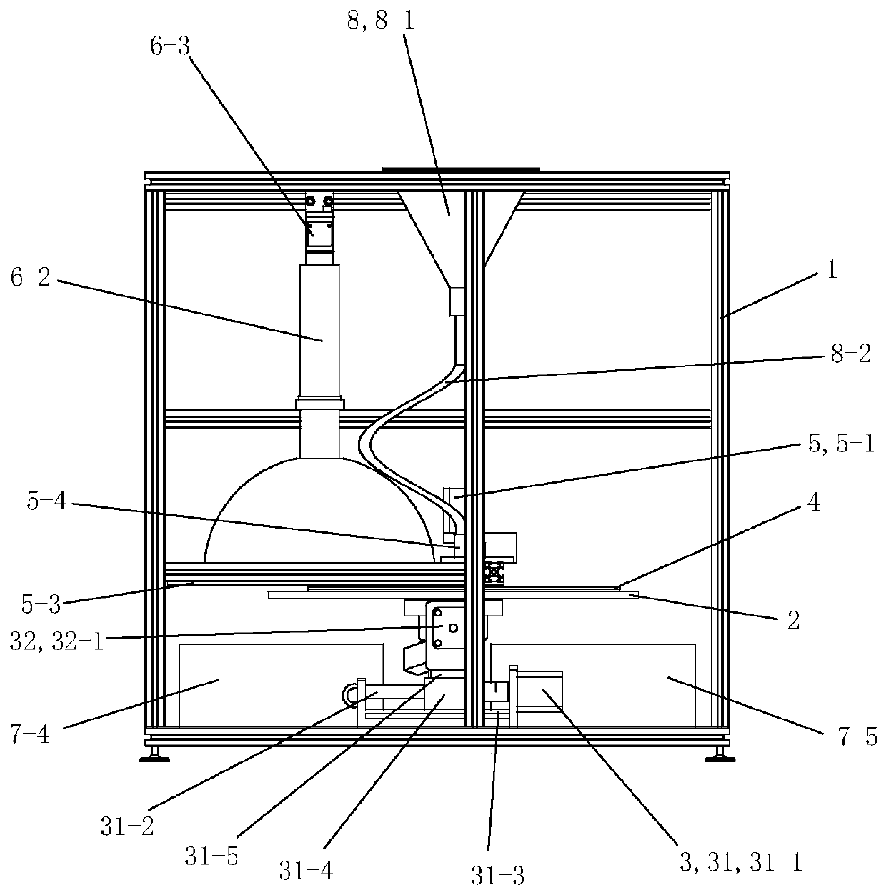
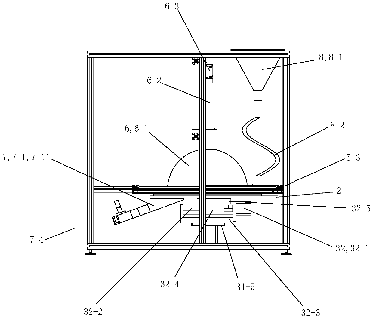
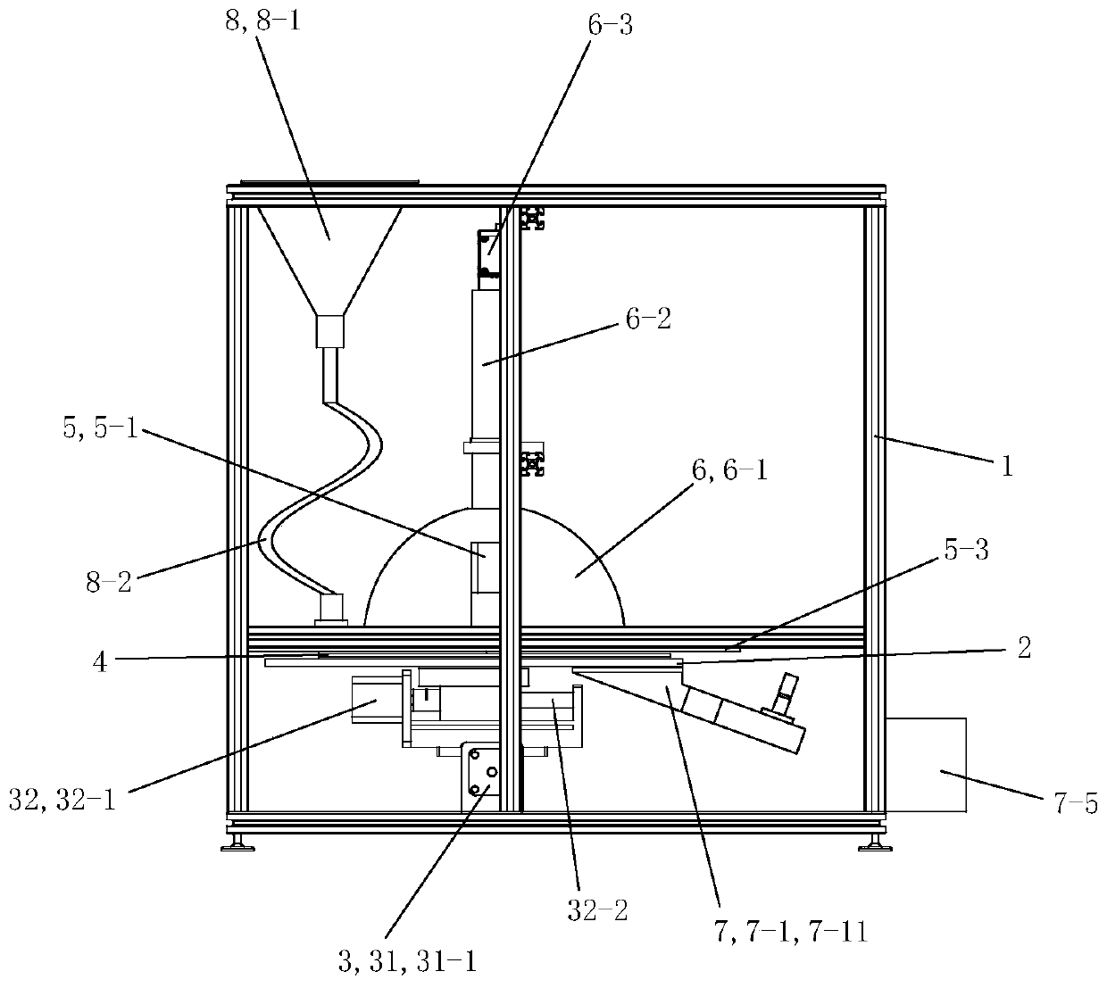
[0053] See Figure 1 to Figure 12 , The ceramic ball surface flaw detection system includes a frame 1, a friction disc 2, a friction disc drive mechanism 3, a sphere tray 4, a tray drive mechanism 5, a machine vision camera 6, a sphere sorting mechanism 7 and a feeding mechanism 8.

[0054] See Figure 1 to Figure 8 , the friction disc 2 is rectangular, and the surface of the friction disc 2 is made of polyurethane material. The rear portion of the friction disc 2 is provided with a blanking opening 2-1 that runs through its upper and lower openings and faces backward.

[0055] See Figure 1 to Figure 7 , The friction disc driving mechanism 3 includes an X-axis driving device 31 and a Y-axis driving device 32 .

[0056] See Figure 1 to Figure 7 , The X-axis driving device 31 includes an X-axis stepping motor 31-1, an X-axis screw rod 31-2, an X-axis slide rail 31-3, an X-axis slider 31-4 and an X-axis connecting seat 31-5.

[0057] The X-axis stepping motor 31-1 is fixed...


PUM

PropertyMeasurementUnit
diameteraaaaaaaaaa

Abstract

The invention discloses a ceramic ball sphere surface defect detection system. The system comprises a frame, a friction disk, a friction disk drive mechanism, a sphere tray, a tray drive mechanism, amachine vision photographing device and a sphere classification mechanism. The tray drive mechanism drives the sphere tray to rotate above the friction disk. The sphere tray is provided with a spherelimiting hole which runs through the sphere tray. The corresponding middle part of a ceramic ball is located in the sphere limiting hole. The corresponding lower part of the ball contacts the frictiondisk. The sphere tray is used to change the position of the ball in a horizontal plane. The ceramic ball can rotate freely in the sphere limiting hole. The friction disk drive device is arranged on the frame. The friction disk drive device drives the friction disk to move in the same horizontal plane. The friction disk enables the ball to freely rotate in place in the sphere limiting hole throughfriction. The machine vision photographing device is used to photograph the surface of the ceramic ball. The sphere classification mechanism is used to separate and collect qualified ceramic balls and unqualified ceramic balls.

Description

technical field [0001] The invention relates to the technical field of surface flaw detection based on machine vision, in particular to a non-contact ceramic ball surface flaw detection system for detecting ceramic balls in bearings. Background technique [0002] Ball bearings are widely used general-purpose mechanical products. The balls are spheres, which are in great demand, and their surface quality directly affects the quality of the bearing. At present, most of the balls used in bearings are made of steel balls. Compared with steel balls, silicon nitride ceramic bearing balls have the characteristics of small thermal expansion coefficient, small friction coefficient, oil-free self-lubrication, high speed, long life, and insulation. It will have broad application prospects in aviation, aerospace and other fields. However, due to the brittleness of ceramic materials, surface defects may occur at various stages of ceramic ball manufacturing and processing, and defects on...

Claims


Application Information

Patent Timeline
Patent Type & Authority Applications(China)
IPC IPC(8): G01N21/89B07C5/00B07C5/02B07C5/36
CPCB07C5/00B07C5/02B07C5/361B07C5/362G01N21/8914
Inventor 王伟辉李军锋王俊献傅艳红朱锦程
Owner CHANGZHOU INST OF OPTOELECTRONICS TECH
Why Eureka
Try Eureka