Directional solidification smelting device and method for refractory high-entropy alloy
A directional solidification, high-entropy alloy technology, used in lighting and heating equipment, charging processing types, furnace components, etc., can solve the problem that the smelting raw materials cannot be in a molten state at the same time, the structure of refractory high-entropy alloys is uneven, and it is difficult to ensure uniform stirring. and other problems, to achieve the effect of good electromagnetic field coupling, low cost, and ensuring consistency
- Summary
- Abstract
- Description
- Claims
- Application Information
AI Technical Summary
Problems solved by technology
Method used
Image

Examples
Embodiment 1
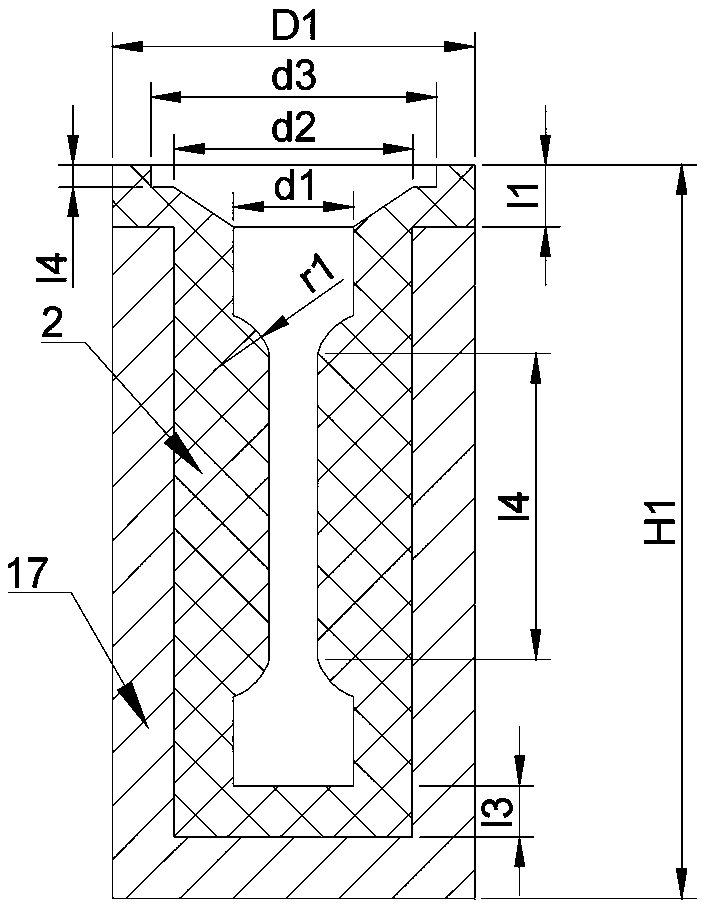
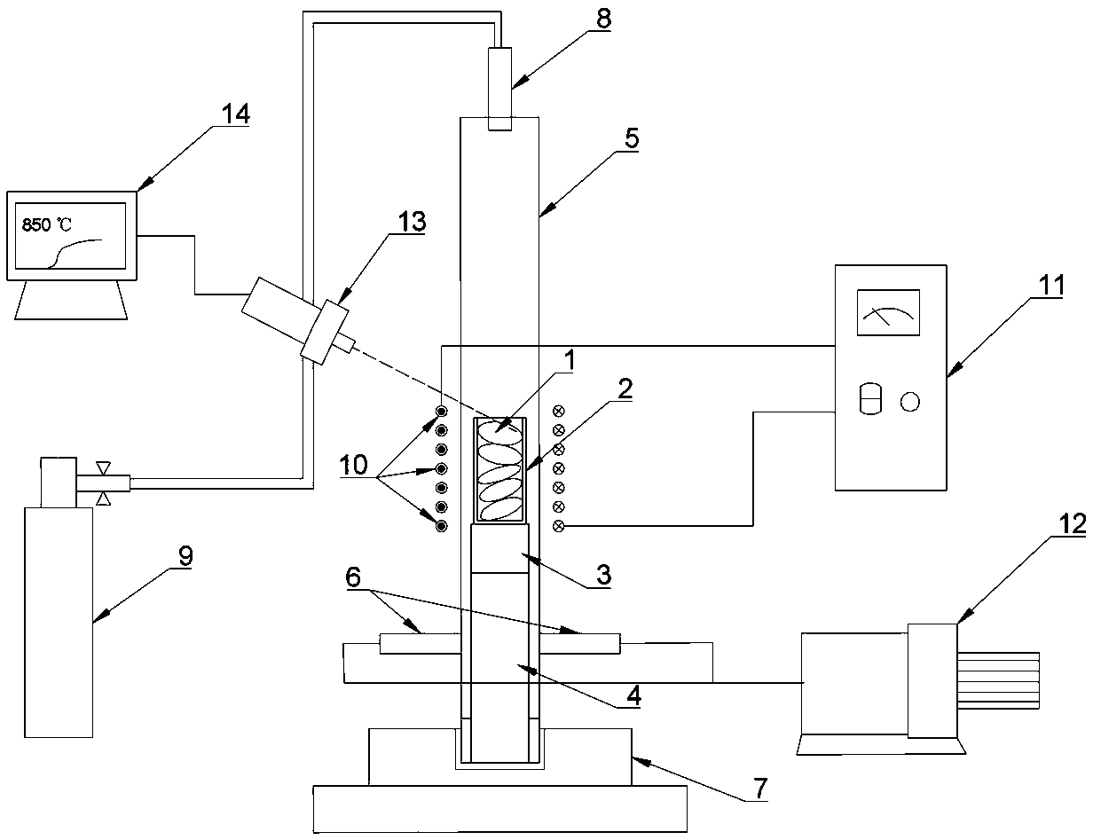
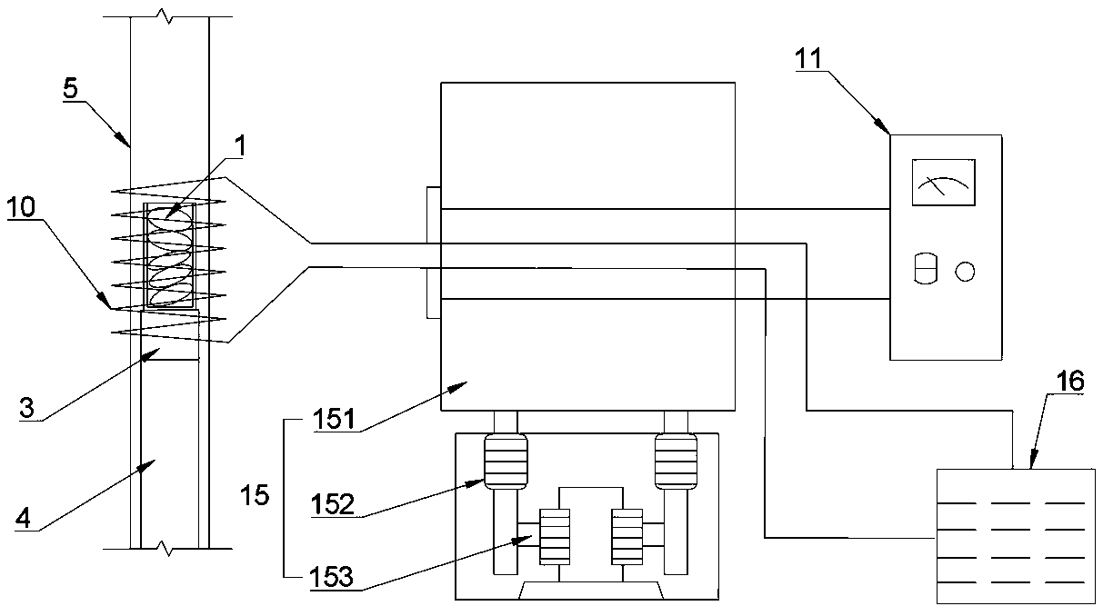
[0053] A directional solidification smelting device for a refractory high-entropy alloy of the present invention comprises a quartz glass tube 5, a melting crucible 2, an induction coil 10 and a melting power supply 11, the melting crucible 2 is equipped with an alloy raw material 1 and is located inside the quartz glass tube 5, The induction coil 10 is connected to the smelting power supply 11 and sleeved on the outside of the quartz glass tube 5 and is used for melting the alloy raw material 1 in the smelting crucible 2. The directional solidification smelting equipment also includes a lifting device 15, and the induction coil 10 is connected to the lifting device 15. Driven by the device 15, it moves up and down along the quartz glass tube 5.
[0054] In this embodiment, the quartz glass tube 5 is a hollow quartz tube, and the quartz glass tube 5 is vertically fixed on the base 7, and the stainless steel flange presses the rubber ring to expand and fit the wall of the quartz...
Embodiment 2
[0075] The directional solidification smelting equipment for the refractory high-entropy alloy used in this embodiment is the same as that in Embodiment 1.
[0076] The directional solidification and smelting method of a refractory high-entropy alloy in this embodiment is roughly the same as in Embodiment 1, the difference is that during induction smelting, the induction coil 10 rises at a speed v 0 It is 1.2mm / s.
[0077] Cut the longitudinal section of the alloy ingot by wire cutting, and observe the size, shape and distribution of shrinkage cavities on the surface after grinding the metallographic phase. The results are as follows: Figure 8 As shown, it can be seen that the shrinkage cavities are mainly distributed in the upper half of the alloy ingot, and the number of shrinkage cavities in the lower half is relatively small.
Embodiment 3
[0079] The directional solidification smelting equipment for the refractory high-entropy alloy used in this embodiment is the same as that in Embodiment 1.
[0080] The directional solidification and smelting method of a refractory high-entropy alloy in this embodiment is roughly the same as in Embodiment 1, the difference is that during induction smelting, the induction coil 10 rises at a speed v 0 It is 3.6mm / s.
[0081] Cut the longitudinal section of the alloy ingot by wire cutting, and observe the size, shape and distribution of shrinkage cavities on the surface after grinding the metallographic phase. The results are as follows: Figure 9 As shown, it can be seen that the distribution of shrinkage cavities inside the alloy ingot is scattered and the number is large, and the main concentration is in the middle of the alloy ingot.
PUM
 Abstract
Description
Claims
Application Information
 - R&D
- Intellectual Property
- Life Sciences
- Materials
- Tech Scout
- Unparalleled Data Quality
- Higher Quality Content
- 60% Fewer Hallucinations
Browse by: Latest US Patents, China's latest patents, Technical Efficacy Thesaurus, Application Domain, Technology Topic, Popular Technical Reports.
© 2025 PatSnap. All rights reserved.Legal|Privacy policy|Modern Slavery Act Transparency Statement|Sitemap|About US| Contact US: help@patsnap.com