
Heat treatment method for reducing steel rail fatigue crack propagation rate

A technology of fatigue crack propagation and heat treatment method, which is applied in heat treatment furnaces, heat treatment equipment, furnace types, etc., can solve the problems of driving safety hazards, reduce the fatigue crack growth rate of rails, etc., and achieve the purpose of improving the service life of rails and reducing the fatigue crack growth rate , easy to promote the effect of the application

Active Publication Date: 2019-12-03
武汉钢铁有限公司
View PDF5 Cites 10 Cited by
  • Summary
  • Abstract
  • Description
  • Claims
  • Application Information

AI Technical Summary

Problems solved by technology

Fatigue crack growth rate is an important index to measure the initiation and growth speed of rail cracks, which is directly related to the service life of rails and driving safety. In view of the problem of excessive fatigue crack growth rate of heat-treated rails and the resulting hidden dangers of driving safety, it is urgent A production method that can effectively reduce the growth rate of rail fatigue cracks is needed

Method used


Image

  • Heat treatment method for reducing steel rail fatigue crack propagation rate
  • Heat treatment method for reducing steel rail fatigue crack propagation rate
  • Heat treatment method for reducing steel rail fatigue crack propagation rate

Examples


Embodiment 1

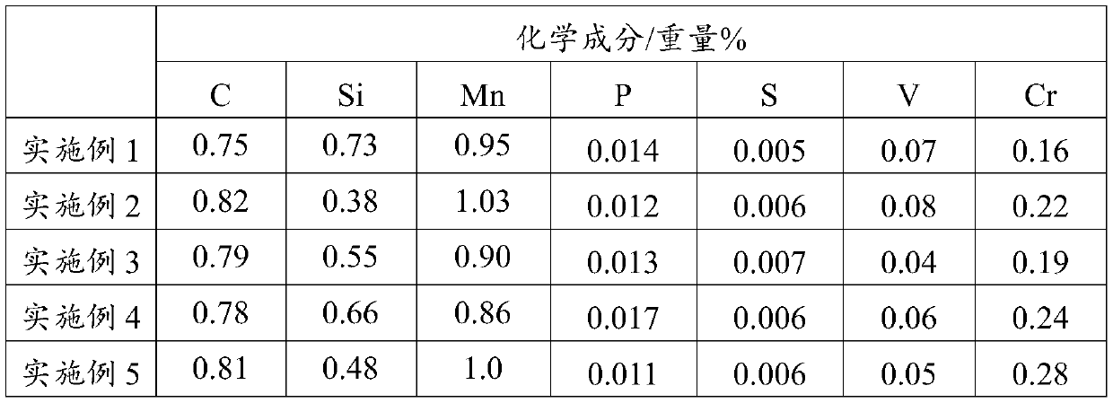
[0036] According to the conventional rail smelting and casting methods, the process includes converter smelting, LF refining, vacuum treatment, and continuous casting. Among them, the basicity of converter slag is controlled at 2.8-4.0; when the molten steel is about 1 / 4, alloys such as silicon, manganese, vanadium and recarburizers are added along with the steel flow, and when the molten steel reaches 3 / 4, the alloys and recarburizers are all Add; LF furnace treatment time should be greater than 35min; RH vacuum degree ≤ 90Pa, pure vacuum treatment time should not be less than 16min, the casting process should be carried out under full protection to prevent contact with air, and the cast billet should be slowly cooled. Then follow the conventional rail rolling method. The steel billet is sent into the walking beam heating furnace for heating and heat preservation. The heating temperature is 1200-1300 ℃, and the heat preservation time is 150-260min. ℃, the final rolling temper...

Embodiment 2-5

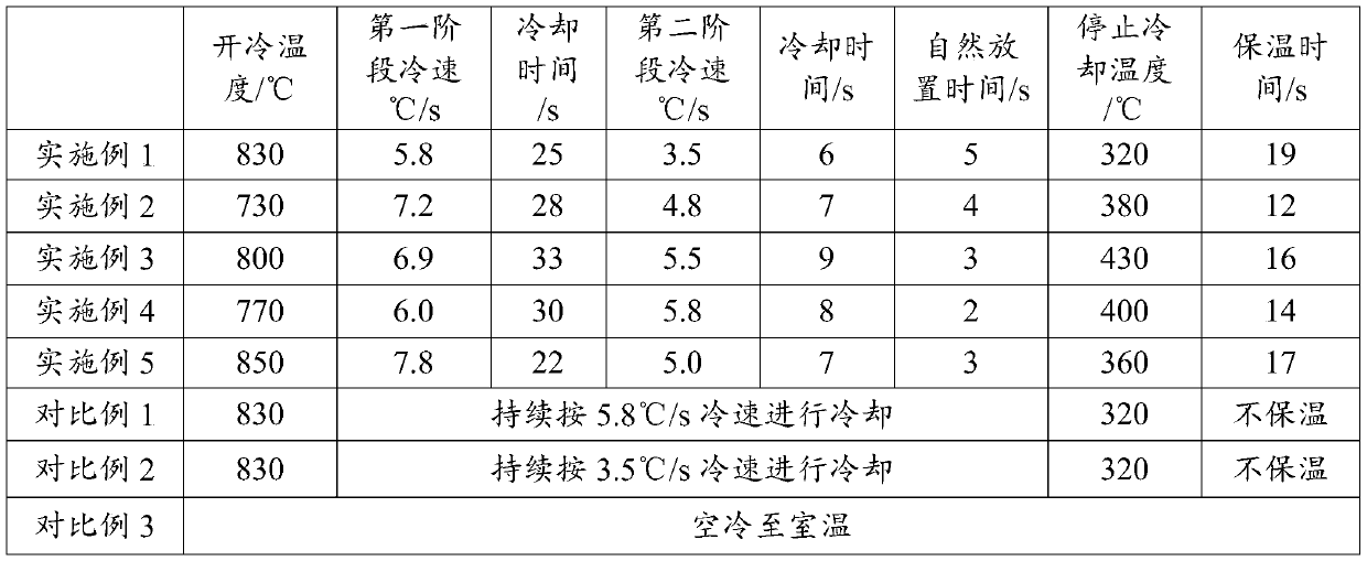
[0038] According to the method of Example 1, the difference is that the specific process parameters of accelerated cooling after rolling are as shown in Table 2 respectively.


PUM


Abstract

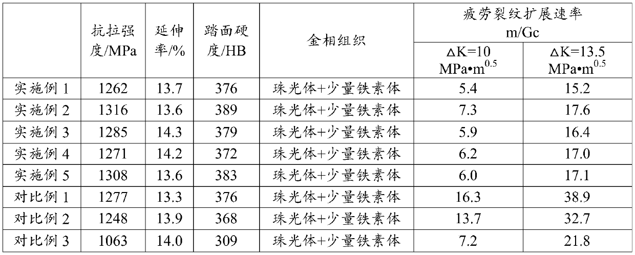
The invention discloses a heat treatment method for reducing the steel rail fatigue crack propagation rate. The heat treatment method comprises the following steps: a hot-rolled steel rail head is subjected to segmented accelerated cooling heat treatment: specifically, the initial cooling temperature is controlled to be 720-860 DEG C, the first-stage rail head cooling speed is 5-8 DEG C / s, and thecooling time is 20-35 s; subsequent second-stage cooling: in this stage, circulating periodic cooling is adopted, firstly, the rail head is cooled in an accelerated manner, wherein the cooling speedis 3-6 DEG C / s, the cooling time is 6-10 s, then accelerated cooling is stopped, the steel rail is naturally placed for 2-5 s, a cooling period is formed, through continuous circulation of said cooling period, when the temperature of the rail head is reduced to 300-450 DEG C, accelerated cooling is stopped, then the rail head is subjected to heat preservation for 10-20 min, and finally the rail head is naturally cooled to the room temperature. In the steel rail obtained through the method, the room-temperature metallographic structure of the whole section is composed of lamellar pearlite and asmall amount of ferrite; the fatigue crack propagation rate can be controlled to be 5-8 m / Gc (delta K = 10 MPa.m < 0.5 >) and 14-18 m / Gc (delta K = 13.5 MPa.m < 0.5 >); the method can be applied to various lines of passenger transportation, passenger and cargo mixed transportation and the like, the service life of the steel rail is prolonged, and the driving safety of the steel rail is improved.

Description

technical field [0001] The invention relates to the technical field of on-line heat treatment rail production, in particular to a heat treatment method for reducing the fatigue crack growth rate of the rail. Background technique [0002] With the rapid development of my country's railways towards high-speed passenger transportation and heavy-duty freight transportation, problems such as rail wear and fatigue damage have increased significantly, seriously affecting the service life of rails and driving safety. On-line heat treatment of rails can effectively improve the wear resistance and fatigue resistance of rails, meet the use requirements of heavy-duty railways and small-radius curved railways, and improve the service life of rails. [0003] At present, rail manufacturers at home and abroad basically use the online heat treatment process to produce heat-treated rails. Using the residual temperature of the hot-rolled rails, the rail head is subjected to online accelerated ...

Claims


Application Information

Patent Timeline
IPC IPC(8): C21D9/06C21D1/78C21D6/00C21D8/00C22C38/02C22C38/04C22C38/24
CPCC21D1/78C21D6/002C21D6/005C21D6/008C21D8/005C21D9/06C21D2211/005C21D2211/009C22C38/002C22C38/02C22C38/04C22C38/24
Inventor 费俊杰周剑华朱敏董茂松郑建国王瑞敏欧阳珉路赵国知
Owner 武汉钢铁有限公司
Learn More