Short-wave full-band broadband multi-channel receiving system

A receiving system and full-band technology, applied in the field of electronic information, can solve problems such as difficult implementation, low detection probability and interception probability, and increased industrial interference, and achieve the effects of expanding dynamic range, high MTBF, and high scanning speed

Inactive Publication Date: 2019-12-03
TONG FANG ELECTRONICS SCI & TECH
View PDF8 Cites 5 Cited by
  • Summary
  • Abstract
  • Description
  • Claims
  • Application Information

AI Technical Summary

Problems solved by technology

However, due to the performance of today's ADC chips, this ideal software radio receiving device is difficult to realize in the real world. The RF signal must be properly filtered and amplified before being sent to the ADC sampling chip.
On the other hand, due to the application of some new technologies such as frequency hopping, burst and spread spectrum communication in modern short-wave communication, the short-wave communication signal has a lower detection probability and interception probability, and it is necessary to require the instantaneous bandwidth of the receiving device to work. The traditional fixed sub-octave preselection filter cannot be used; secondly, because the short-wave communication signal is mainly transmitted through the reflection of the ionosphere, it is greatly affected by ionosphere activities and multipath effects, resulting in The signal arriving at the receiving end is usually very weak, which puts forward higher requirements on the noise performance of the receiving equipment; finally, due to the increase of various radio stations and industrial interference, the probability of false response of the receiving equipment is greatly increased. Shortwave receiving equipment puts forward the requirements of broadband, high sensitivity and large dynamic range
[0003] For the problems in related technologies, no effective solutions have been proposed yet

Method used


Image

  • Short-wave full-band broadband multi-channel receiving system
  • Short-wave full-band broadband multi-channel receiving system
  • Short-wave full-band broadband multi-channel receiving system

Examples


Embodiment Construction

[0023] The following will clearly and completely describe the technical solutions in the embodiments of the present invention with reference to the accompanying drawings in the embodiments of the present invention. Obviously, the described embodiments are only some, not all, embodiments of the present invention. All other embodiments obtained by persons of ordinary skill in the art based on the embodiments of the present invention belong to the protection scope of the present invention.

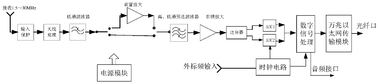
[0024] Such as figure 1 As shown, a short-wave full-band broadband multi-channel receiving system according to an embodiment of the present invention is mainly composed of a radio frequency signal processing subsystem, a clock circuit, a digital signal processing subsystem and a power supply module.

[0025] The RF signal processing subsystem consists of sequentially connected input protection circuit, antenna attenuation circuit, low-pass filter, mode switching circuit, high / low-pass presele...


PUM


Abstract

The invention relates to a short-wave full-band broadband multi-channel receiving system. The system comprises a power supply module, a radio frequency signal processing subsystem, a digital signal processing subsystem and a clock circuit, the radio frequency signal processing subsystem comprises an input protection circuit, an antenna attenuation circuit, a low-pass filter, a mode switching circuit, a high/low-pass preselection filter and a full-band high-linearity low-noise amplifier which are connected in sequence. The digital signal processing subsystem comprises two ADC acquisition circuits and a digital signal processing module which are connected in sequence. A radio frequency signal processed by the full-band high-linearity low-noise amplifier is divided into two parts through thepower divider and then input into the two ADC acquisition circuits for sampling processing, the clock circuit is connected with the two ADC acquisition circuits and the digital signal processing module, and the digital signal processing module is connected with an Ethernet transmission module. According to the invention, the problems of insufficient frequency band coverage, insufficient dynamic range, false response and the like of the current short-wave receiving equipment are effectively solved.

Description

technical field [0001] The invention relates to the technical field of electronic information, in particular to a short-wave full-band broadband multi-channel receiving system. Background technique [0002] An ideal software radio receiving device requires that the digital processing interface should be as close as possible to the root of the antenna, that is, it can directly perform radio frequency sampling on the signal received by the antenna, and then load the corresponding software module in the digital domain to realize signal identification. demodulation, decoding and other functions. However, due to the performance of today's ADC chips, this ideal software radio receiving device is difficult to realize in the real world. The RF signal must be properly filtered and amplified before being sent to the ADC sampling chip. On the other hand, due to the application of some new technologies such as frequency hopping, burst and spread spectrum communication in modern short-w...

Claims


Application Information

Patent Timeline
Patent Type & Authority Applications(China)
IPC IPC(8): H04B1/26H04B1/16H04B1/00
CPCH04B1/0057H04B1/006H04B1/1615H04B1/1638H04B1/26
Inventor 赵智兵徐保根彭志华
Owner TONG FANG ELECTRONICS SCI & TECH
Why Eureka
Try Eureka