Method and device for high-temperature ultrahigh-pressure reheating waste heat power generation
A technology of waste heat power generation and ultra-high pressure, which is applied in the field of high-temperature and ultra-high pressure reheat waste heat power generation method and its device, can solve the problems of low energy utilization rate, achieve the effects of improving thermal cycle efficiency, low operating costs, and saving resources
- Summary
- Abstract
- Description
- Claims
- Application Information
AI Technical Summary
Problems solved by technology
Method used
Image

Examples
Embodiment 1
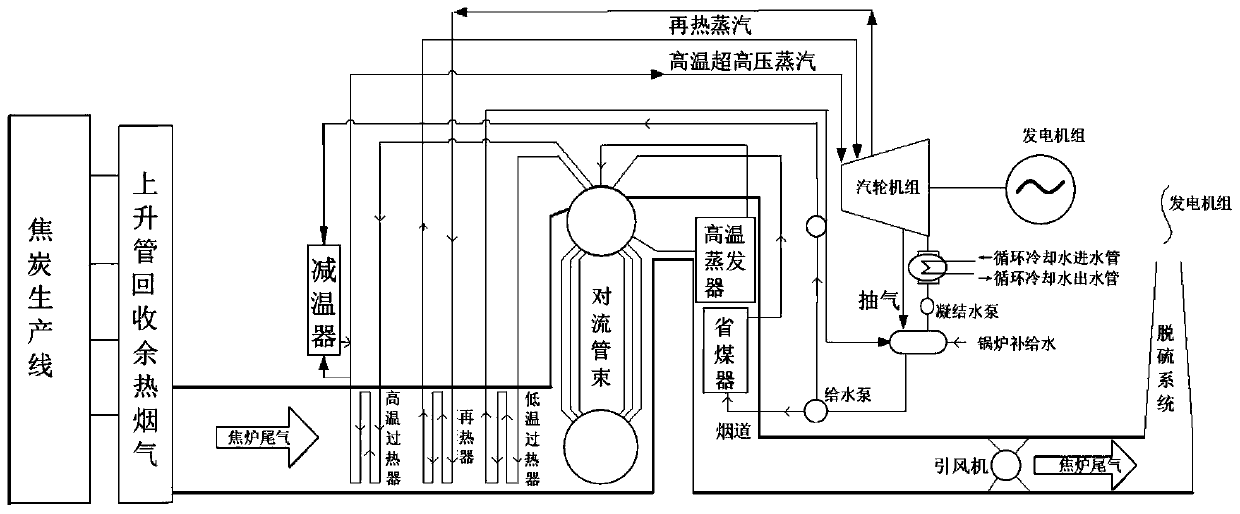
[0032] A high-temperature and ultra-high-pressure reheat waste heat power generation method, such as figure 1 shown, including the following steps:
[0033] S1: Use the induced draft fan to send the 1000-1170°C rising pipe high-temperature flue gas generated during the production process of the coke production line to the high-temperature and ultra-high pressure reheating waste heat boiler through the gas collection pipe for heat exchange to generate 13.7MPa, 540°C high-temperature and ultra-high pressure steam ;
[0034] S2: 13.7MPa, 540°C high-temperature ultra-high pressure steam generated by the reheating waste heat boiler drives the operation of the pure condensing steam turbine, while the 0.4MPa, 152°C low-pressure steam generated by the boiler is used for the deaerator of the waste heat boiler;
[0035] S3: The 2.9MPa, 350°C gas produced by the high-temperature and ultra-high-pressure steam in the pure condensing turbine is sent to the boiler for reheating. After rehea...
PUM
 Abstract
Description
Claims
Application Information