Welding method for cold plate component

A welding method and cold plate technology, applied in welding equipment, auxiliary welding equipment, welding/cutting auxiliary equipment, etc., can solve the problem of high product size and apparent quality, aluminum parts that cannot be soldered with tin-lead, aluminum parts and The surface of the copper tube is easy to oxidize and other problems, so as to achieve the effect of long reflow time, good reliability and guaranteed thermal conductivity

Active Publication Date: 2019-12-10
HUBEI SANJIANG SPACE XIANFENG ELECTRONICS&INFORMATION CO LTD
View PDF9 Cites 3 Cited by
  • Summary
  • Abstract
  • Description
  • Claims
  • Application Information

AI Technical Summary

Problems solved by technology

[0011] 3) If tin-lead welding with a melting point of 183°C is used, firstly, aluminum parts cannot be soldered with tin-lead, and secondly, because the surface of aluminum parts and copper pipes is easy to oxidize, once an oxide layer appears, it cannot be welded
[0012] 4) Because tin-lead soldering needs to use flux to increase wettability, but as shown in Figure 1, there is a sealed space between the hot bend tube, the substrate and the thermal grease. If conventional tin-lead solder paste is used, the flux will evaporate during the soldering process. If it cannot be discharged, it will inevitably lead to a large number of welding voids, which will cause poor contact of the hot elbow and eventually affect heat dissipation
[0013] 5) Because tin-lead solder is used for reflow welding of pure metal structural parts, the design of its welding curve is completely different from the welding of ordinary circuit boards, and the requirements for the size and appearance quality of products after welding are very high. What kind of welding method is used to ensure that the products The quality and reliability of the

Method used


Image

  • Welding method for cold plate component
  • Welding method for cold plate component
  • Welding method for cold plate component

Examples


Embodiment Construction

[0043]In order to make the object, technical solution and advantages of the present invention clearer, the present invention will be further described in detail below in conjunction with the accompanying drawings and embodiments. It should be understood that the specific embodiments described here are only used to explain the present invention, not to limit the present invention. In addition, the technical features involved in the various embodiments of the present invention described below can be combined with each other as long as they do not constitute a conflict with each other.

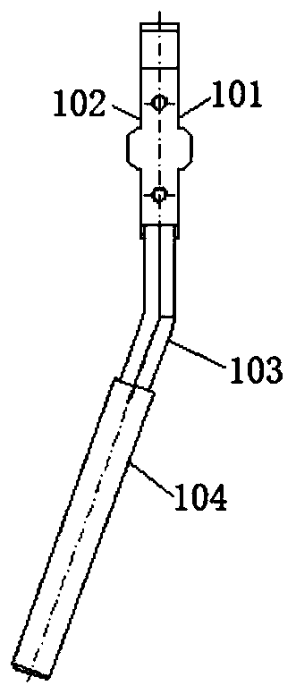
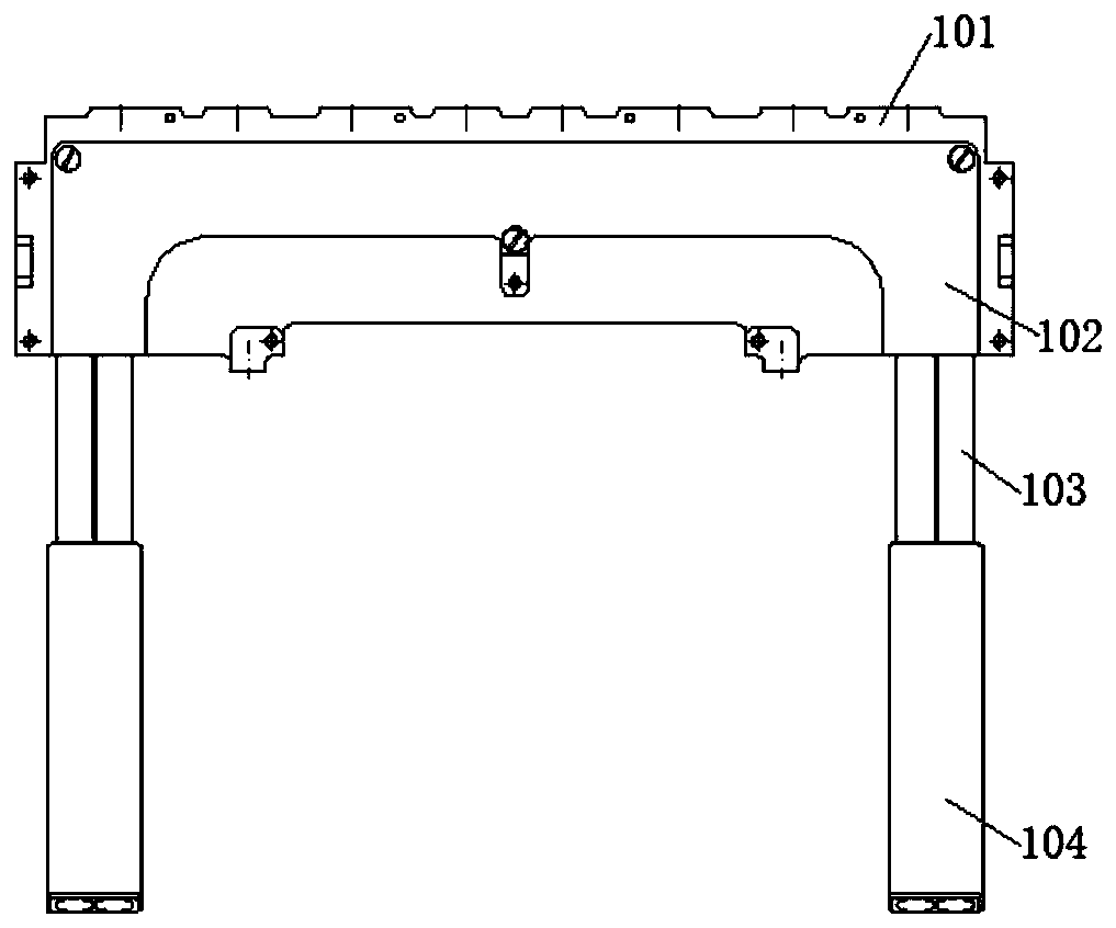
[0044] Referring to the accompanying drawings, a welding method of a cold plate assembly, the cold plate assembly includes a cold plate base 101, a cold plate cover 102, a hot bend 103 and a heat conducting finger 104, the maximum heat-resistant temperature of the hot bend 103 is not over 220°C and the hot bending tube 103 includes an aluminum inner tube, a phase change material installed in the ...


PUM

PropertyMeasurementUnit
thermal resistanceaaaaaaaaaa
thicknessaaaaaaaaaa
thicknessaaaaaaaaaa

Abstract

The invention discloses a welding method for a cold plate component. The cold plate component comprises a cold plate substrate, a cold plate cover, a hot bent pipe, and thermal conductive fingers. Thewelding method comprises the following steps of: step (1). nickel plating, to be specific, plating the interior of a first groove of the cold plate substrate, the interior of a second groove of the cold plate cover, the middle position of the hot bent pipe, each end of the hot bent pipe and each thermal conduction finger with nickel to form nickel layers; step (2). applying tin, to be specific, applying a layer of solder paste to each of the nickel layers in step (1); step (3). assembling, to be specific, inserting the hot bent pipe into the first groove of the cold plate substrate and the second groove of the cold plate cover, respectively embedding the two ends of the hot bent pipe into one thermal conductive finger, thereby forming a cold plate assembly; and step (4). heating, to be specific, putting the cold plate assembly in step 3) into a reflow oven for reflow soldering. The cold plate component is subjected to nickel plating and tin applying surface treatment, so that metal parts on the cold plate component can be soldered by adopting low temperature tin-lead solder to ensure the thermal conductivity and welding quality of the cold plate component.

Description

technical field [0001] The invention belongs to the technical field of welding, and more specifically relates to a welding method of a cold plate assembly. Background technique [0002] refer to Figure 1a , Figure 1b ,The cold plate assembly is an important part of the thermal control module. The cold plate base and the cold plate cover of the cold plate assembly are embedded with hot elbows. The hot elbows are connected to the back of the TR module and the heat conducting fingers. 1. The hot bending tube and the heat conducting finger must be connected seamlessly and reliably to effectively reduce contact thermal resistance and ensure good heat transfer effect. Cold plate components have high requirements on welding quality and structural dimensional accuracy. [0003] The current problems faced by cold plate assembly welding: [0004] 1) Because the cold plate assembly has a three-dimensional space structure as a whole, the dimensional accuracy requirements are high, ...

Claims


Application Information

Patent Timeline
Patent Type & Authority Applications(China)
IPC IPC(8): B23K1/00B23K1/008B23K1/20B23K3/08B23K37/04
CPCB23K1/0008B23K1/008B23K1/20B23K3/087
Inventor 秦钢皮华辉刘祚全刘冬洋刘轩宇
Owner HUBEI SANJIANG SPACE XIANFENG ELECTRONICS&INFORMATION CO LTD
Why Eureka
Try Eureka