A limit structure for intelligent printing machine

A limiting structure and technology of printing presses, applied in printing presses, general parts of printing machinery, printing and other directions, can solve the problems of general positioning effect of substrates, difficult to meet requirements, etc., and achieve difficult displacement, good integrity, and fit. good effect

Active Publication Date: 2021-06-01
杭州敏邦实业有限公司
View PDF0 Cites 0 Cited by
  • Summary
  • Abstract
  • Description
  • Claims
  • Application Information

AI Technical Summary

Problems solved by technology

[0003] The positioning effect of the current printing machine on the substrate is average, and it is difficult to meet the needs of the market

Method used


Image

  • A limit structure for intelligent printing machine
  • A limit structure for intelligent printing machine
  • A limit structure for intelligent printing machine

Examples


Embodiment 1

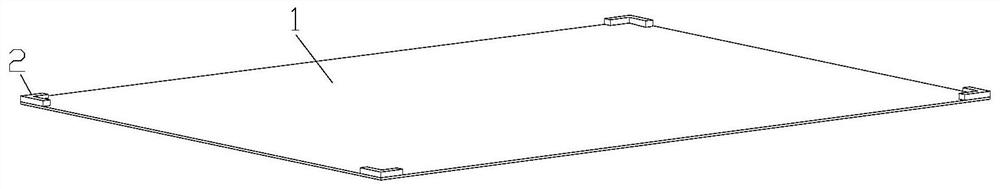
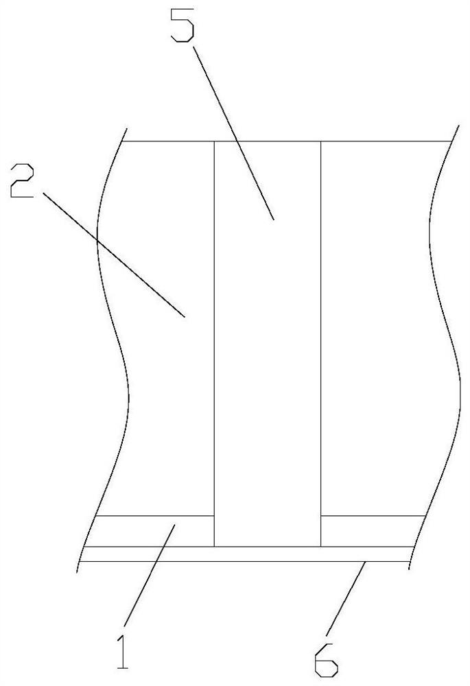
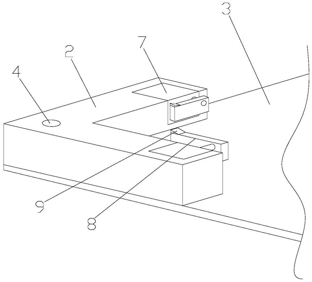
[0044] Such as Figure 1-4 As shown, a limiting structure for an intelligent printing machine includes an electrostatic adsorption film 1 for installation on a conveyor belt, and limit blocks 2 are arranged at four corners of the electrostatic adsorption film 1, and the limiting The positioning block 2 is arranged in an L shape, and the limiting block 2 is fixedly connected with the electrostatic adsorption film 1. Both ends of the limiting block 2 are provided with clamping devices for clamping the substrate. The electrostatic adsorption film 1 and the limit block 2 form a placement groove 3 that fits with the substrate, and the electrostatic adsorption film is composed of 130 parts of polyvinyl chloride resin, 45 parts of polytetrafluoroethylene, and dioctyl phthalate in proportions by weight. 2 parts, 7 parts of ethyl cellulose, 3 parts of epoxidized soybean oil, 5 parts of barium titanate, 1 part of 2-hydroxypropyl acrylate, 6 parts of hydrotalcite, 5 parts of paraffin, 1 ...

Embodiment 2

[0056] Such as Figure 1-4 As shown, a limiting structure for an intelligent printing machine includes an electrostatic adsorption film 1 for installation on a conveyor belt, and limit blocks 2 are arranged at four corners of the electrostatic adsorption film 1, and the limiting The positioning block 2 is arranged in an L shape, and the limiting block 2 is fixedly connected with the electrostatic adsorption film 1. Both ends of the limiting block 2 are provided with clamping devices for clamping the substrate. The electrostatic adsorption film 1 and the limit block 2 form a placement groove 3 that fits with the substrate, and the electrostatic adsorption film is composed of 150 parts of polyvinyl chloride resin, 65 parts of polytetrafluoroethylene, and dioctyl phthalate in proportions by weight. 4 parts, 10 parts of ethyl cellulose, 5 parts of epoxidized soybean oil, 7 parts of barium titanate, 3 parts of 2-hydroxypropyl acrylate, 8 parts of hydrotalcite, 7 parts of paraffin w...


PUM


Abstract

The invention discloses a limiting structure for an intelligent printing machine, which includes an electrostatic adsorption film for installation on a conveyor belt, and limit blocks are arranged at four corners of the electrostatic adsorption film, and the limit blocks are in the shape of L-shaped setting, the limit block is fixedly connected with the electrostatic adsorption film, and both ends of the limit block are provided with clamping devices for clamping the substrate, and the electrostatic adsorption film and the limit block are formed to be compatible with the printing material. A placement tank that fits the object, and the electrostatic adsorption film is composed of 130-150 parts of polyvinyl chloride resin, 45-65 parts of polytetrafluoroethylene, 2-4 parts of dioctyl phthalate, and 7-10 parts of base cellulose, 3-5 parts of epoxy soybean oil, 5-7 parts of barium titanate, 1-3 parts of 2-hydroxypropyl acrylate, 6-8 parts of hydrotalcite, 5-7 parts of paraffin, 1-3 parts of dibutyltin dilaurate, 1-3 parts of tetrabutyltin, 7-11 parts of nano-neodymium oxide and 3-8 parts of fluoroalkyl polyether modified polysiloxane; The positioning structure has a good positioning effect on the substrate.

Description

technical field [0001] The invention relates to a position-limiting structure for an intelligent printing machine. Background technique [0002] A machine for printing text and images. Modern printing machines are generally composed of plate loading, ink application, embossing, paper feeding and other mechanisms. Its working principle is: first make the printing plate of the text and image to be printed, install it on the printing machine, and then apply the ink to the place where the text and image are on the printing plate manually or by the printing machine, and then transfer it directly or indirectly Printing onto paper or other substrate to reproduce the same print as the printing plate. The invention and development of the printing press played an important role in the spread of human civilization and culture. [0003] The current printing machine has a mediocre positioning effect on the substrate, which is difficult to meet the needs of the market. Contents of th...

Claims


Application Information

Patent Timeline
Patent Type & Authority Patents(China)
IPC IPC(8): B41F21/00C08L27/06C08L27/18C08L1/28C08L91/00C08L91/06C08L83/12C08K13/02C08K5/12C08K3/26C08K3/22C08K5/57C08J5/18
CPCB41F21/00C08J5/18C08J2327/06C08J2401/28C08J2427/18C08J2483/12C08J2491/00C08J2491/06C08K3/26C08K5/12C08K5/57C08K13/02C08K2003/221C08K2201/011
Inventor 不公告发明人
Owner 杭州敏邦实业有限公司
Why Eureka
Try Eureka