Tire centring and rotating scanning system and tire centring and rotating scanning data pickup method

A tire and data technology, which is applied to the tire centering and rotating tracking system and its data pickup field, can solve the problems of long data consumption, loss of code scanning function, and small field of view coverage, and achieves rapid pickup and recording. Production cost, effect of improving specification range

Pending Publication Date: 2019-12-17
鞍山彩盛机械制造有限公司
View PDF0 Cites 1 Cited by
  • Summary
  • Abstract
  • Description
  • Claims
  • Application Information

AI Technical Summary

Problems solved by technology

If a single-head code reader is used to scan, the scanner's field of view coverage is small, and it takes a long time to read data for a single time, and changes to the production line are required; hand-held scanners need to be manually scanned one by one, and the scanning efficiency Low, which increases time cost and labor cost
In order to solve the problem that the single-head scanner has a small field of view coverage and takes a long time to read data for a single time, a tire scanning device using a tire code reading network has emerged. This device is installed above the tire conveyor roller. A set of scanners (generally 6) can expand the scanning range to improve the scanning efficiency, but the cost of this scanning device is greatly increased. The unit price of high-quality scanners is about 30,000 yuan, while a set of 6 scanners The cost is nearly 200,000 yuan, which increases the financial burden of users
Furthermore, this code scanning device adopts a fixed structure, and when the tire specification exceeds the scanning range of the set code reading network, it loses the code scanning function

Method used


Image

  • Tire centring and rotating scanning system and tire centring and rotating scanning data pickup method
  • Tire centring and rotating scanning system and tire centring and rotating scanning data pickup method
  • Tire centring and rotating scanning system and tire centring and rotating scanning data pickup method

Examples


Embodiment Construction

[0026] In the following, the preparation method of the present invention will be further described in conjunction with examples:

[0027] In the description of the present invention, it should be noted that the terms "installation", "connected" and "connected" should be understood in a broad sense, unless otherwise clearly specified and limited. For example, they can be fixed or detachable. Connected or integrally connected; it can be directly connected or indirectly connected through an intermediary. For those of ordinary skill in the art, the specific meanings of the above-mentioned terms in the present invention can be understood in specific situations.

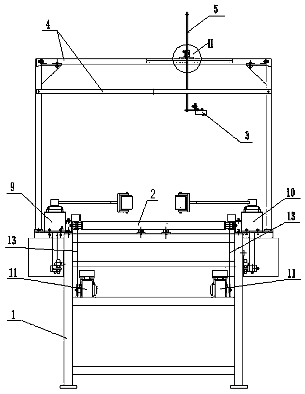
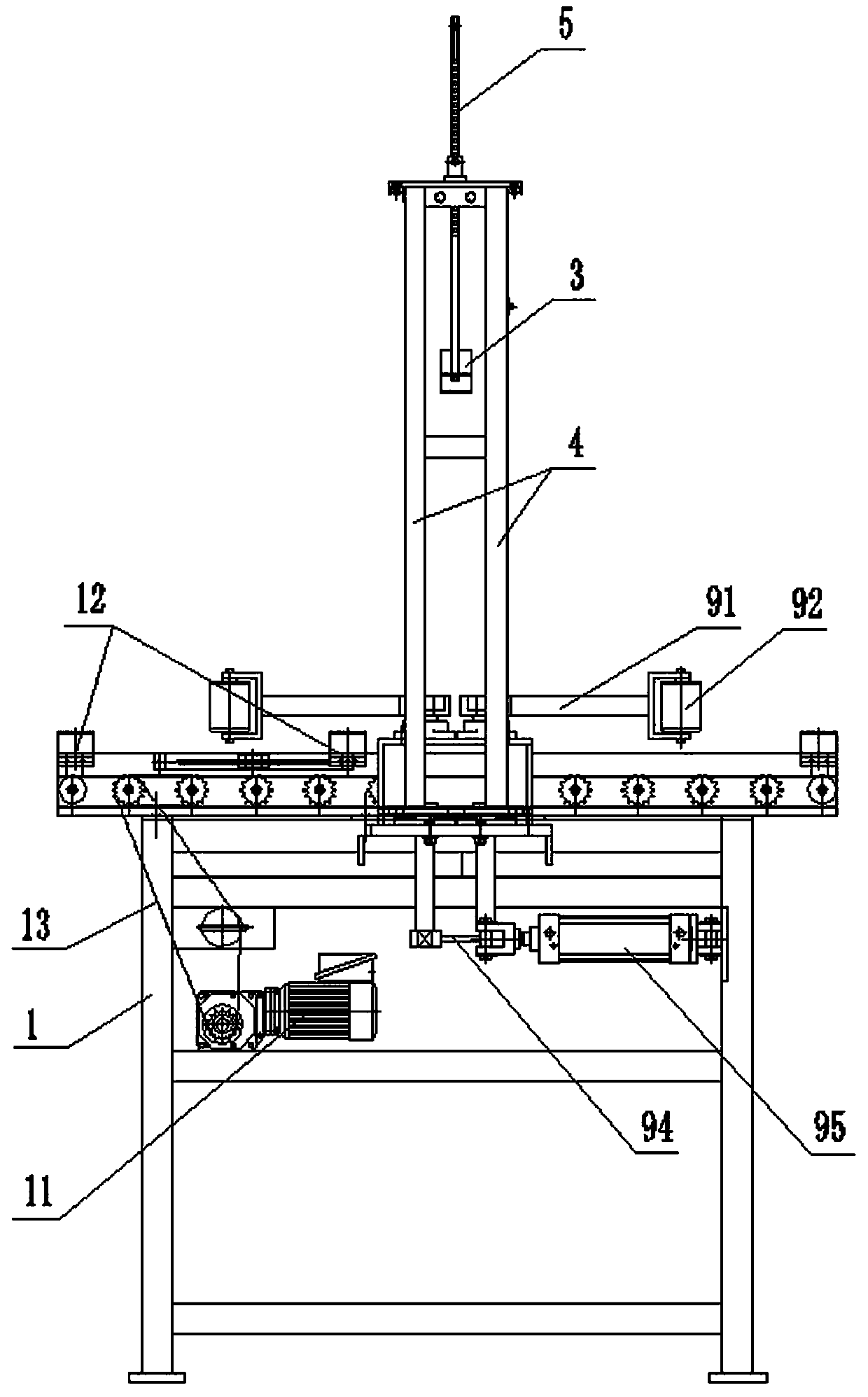
[0028] see figure 1 , figure 2 , Is a schematic diagram of the structure of an embodiment of the tire automatic tracking and scanning device of the present invention, including the main frame 1, the conveying roller 2, the scanner 3, the scanner bracket 4, the PC operating terminal and the PLC electrical control system. The ma...


PUM


Abstract

The invention belongs to the technical field of tire production and particularly relates to a tire centring and rotating scanning system and a tire centring and rotating scanning data pickup method. The tire centring and rotating scanning system is characterized in that the tire centring and rotating scanning system comprises a conveying channel and an automatic identifying device, when a to-be-detected tire carrying an identity information carrier reaches the middle of the conveying channel along the conveying channel, the tire rotates, the automatic identifying device located above the tireautomatically identifies identity information in the identity information carrier on the tire, the tire stops rotating within the set time of 0.5-5 seconds after the information is identified, and theto-be-detected tire is sent out through the conveying channel. Compared with the prior art, the tire centring and rotating scanning system and the tire centring and rotating scanning data pickup method have the advantages that (1) fully-automatic unmanned operation is achieved; and (2) the tire identity information is rapidly picked up and recorded, the uniqueness of tire identity in the whole tire production process is ensured, in the whole life period of the tire, the identity can still serve as the basis of various data applications such as quality analysis, process evaluation analysis andcustomer analysis, and quality improvement of a product and fine management of a sale scheme are facilitated.

Description

Technical field [0001] The invention belongs to the technical field of tire production, and in particular relates to a tire centering rotary tracking system and a data picking method thereof specially arranged on the feeding side of process detection equipment such as tire quality and performance. Background technique [0002] A tire is a ring-shaped rubber product used on various vehicles or machinery. Tires are usually used under complex and harsh conditions. They are subjected to various deformations, loads, forces, and high and low temperature effects during driving. Therefore, they must have high load-bearing performance, traction performance, and cushioning performance. At the same time, they also require high Wear resistance and flex resistance, as well as low rolling resistance and heat build-up, according to statistics, half of the world's rubber output is used to produce tires. [0003] The production of tires usually requires the following processes: banburying process,...

Claims


Application Information

Patent Timeline
Patent Type & Authority Applications(China)
IPC IPC(8): B65G13/06B65G47/90B65G43/00G06K17/00
CPCB65G13/06B65G43/00B65G47/90G06K17/0022
Inventor 王宏宇黄继平张子军裴建新
Owner 鞍山彩盛机械制造有限公司
Why Eureka
Try Eureka