Inner hole laser cladding height control system and method

A technology of laser cladding and height control, which is applied in the coating process and coating of metal materials, and can solve the problems that the distance between the processing head and the workpiece surface cannot be adjusted in real time, the observation of the workpiece surface is difficult, and the surface distance changes.

Inactive Publication Date: 2019-12-27
NANJING INST OF ADVANCED LASER TECH
View PDF2 Cites 0 Cited by
  • Summary
  • Abstract
  • Description
  • Claims
  • Application Information

AI Technical Summary

Problems solved by technology

[0003] At present, when laser cladding inner hole parts with large aspect ratio, it is difficult to observe the surface of the workpiece, and the distance between the processing head and the surface of the workpiece cannot be adjusted in real time.
The laser cladding spot in the inner hole is generally small. Even if the distance between the processing head and the surface of the workpiece changes slightly, the converging point of the nozzle powder will move up and down relative to the molten pool, causing the powder outside the molten pool to be unable to be melted by the laser; There may be random unevenness and some non-circular situations in the inner hole wall of the repaired part. If the height of the inner hole processing head is fixed, the distance between the processing head and the part surface will change, causing the powder gathering point to change up and down in the molten pool, not only It will affect the quality of inner hole cladding and seriously reduce the utilization rate of powder

Method used


Image

  • Inner hole laser cladding height control system and method
  • Inner hole laser cladding height control system and method
  • Inner hole laser cladding height control system and method

Examples


Embodiment Construction

[0045] The present invention will be further described below in conjunction with the accompanying drawings.

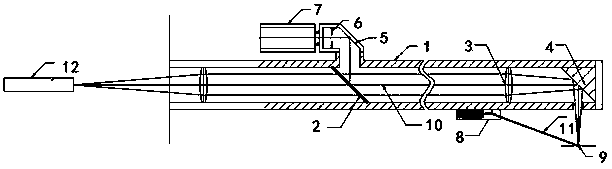
[0046] The invention discloses an inner hole laser cladding height control system, which includes a control system and an inner hole cladding head. The control system includes an external CCD image sensor 7, a digital processing system and a robot control system.

[0047] Such as figure 1As shown, the inner hole cladding head includes a first housing 1, a beam splitter 2, a focusing mirror 3, a reflecting copper mirror 4, a reflecting mirror 5, an adjustable diaphragm 6, an indicator light emitter 8 and a laser emitter 12; The beam splitter 2, the focusing mirror 3 and the reflective copper mirror 4 are sequentially arranged in the first housing 1, and a hole is opened above the first housing 1 between the beam splitter 2 and the focusing mirror 3, and the reflective mirror 5 is sequentially arranged , an adjustable diaphragm 6, and then connected with an external CCD...


PUM


Abstract

The invention discloses an inner hole laser cladding height control system. The inner hole laser cladding height control system comprises a control system body and an inner hole cladding head. For aninner hole laser cladding height control method, a space right-angle coordinate system is built, an indication light beam deviates towards the laser scanning direction by the proper distance, the actual deviation amount of light spots of the indication light beam relative to a molten pool is obtained in a CCD image, according to the mathematic relation between the deviation distance of the light spots of the indication light beam and the deviation distance of the workpiece surface, the deviation between the actual distance of the inner hole cladding head and the workpiece surface and the standard distance is obtained through calculation, and the inner hole cladding head is controlled to be subjected to height adjusting. The inner hole machining head height is adjusted in real time, and therefore the distance between an inner hole machining head and the workpiece surface is kept constant, it is ensured that powder of a cladding head nozzle is gathered in the molten pool, the inner holecladding quality is improved, and the powder use rate is improved.

Description

technical field [0001] The invention relates to the technical field of laser cladding, in particular to a system and method for controlling the laser cladding height of an inner hole. Background technique [0002] Laser cladding refers to placing the selected coating material on the surface of the cladding substrate in different ways of adding materials, melting it and the thin layer of the substrate surface at the same time through laser irradiation, and forming a very low dilution after rapid solidification. The surface coating that is metallurgically combined with the substrate is a process method that significantly improves the wear resistance, corrosion resistance, heat resistance, oxidation resistance and electrical properties of the base surface, so as to achieve the purpose of surface modification or repair, which not only satisfies the specific needs of the material surface Performance requirements, but also save a lot of precious elements. [0003] At present, whe...

Claims


Application Information

Patent Timeline
Patent Type & Authority Applications(China)
IPC IPC(8): C23C24/10
CPCC23C24/10
Inventor 王凯高雪松肖猛刘爽吕非
Owner NANJING INST OF ADVANCED LASER TECH
Why Eureka
Try Eureka