
Method for manufacturing relative humidity sensor and relative humidity sensor

A relative humidity and sensor technology, applied in instruments, scientific instruments, measuring devices, etc., can solve the problems of heat sensitivity, low glass transition temperature, polymer materials not suitable for high temperature, etc., to achieve simplified overall assembly, not easy to aging, small volume effect

Pending Publication Date: 2019-12-27
梅斯法国公司
View PDF3 Cites 0 Cited by
  • Summary
  • Abstract
  • Description
  • Claims
  • Application Information

AI Technical Summary

Problems solved by technology

[0006] However, relative humidity sensors based on organic materials are inherently subject to degradation due to chemical aging of the material and are thermally sensitive compared to other materials due to the lower glass transition temperature.
Furthermore, polymeric materials are not suitable to withstand high temperatures, such as 300 °C or higher, and the structural degradation corresponds to delamination caused by the melting of the metal layer of the sensor

Method used


Image

  • Method for manufacturing relative humidity sensor and relative humidity sensor
  • Method for manufacturing relative humidity sensor and relative humidity sensor
  • Method for manufacturing relative humidity sensor and relative humidity sensor

Examples


Embodiment Construction

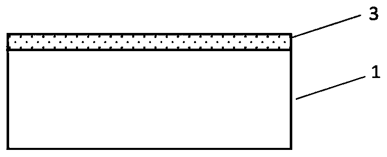
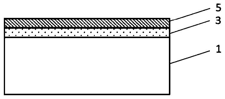
[0032] Figures 1a-1e A method of manufacturing a relative humidity sensor according to a first embodiment of the present invention is shown. It shows the formation of one relative humidity sensor, however it should be understood that the process described is a microfabrication process which allows multiple sensor structures to be formed simultaneously on one substrate (eg, one wafer).

[0033] In the following process steps, the various layers necessary to construct the relative humidity sensor will be formed. Figure 1a A substrate 1 is shown, which may be a silicon substrate with or without an oxide layer on its surface, a sapphire substrate, or any other suitable substrate used in a micromachining line. As an alternative, application specific integrated circuits (ASICs) can also be used as starting material for the method according to the invention.

[0034] Such as Figure 1b As shown, a layer is formed on or over the substrate 1 and serves as the first electrode 3 . T...


PUM


Abstract

The present invention relates to a method of manufacturing a relative humidity sensor comprising the step of: a) providing a first electrode (3) on or over a substrate (1), b) providing a non-porous inorganic dielectric layer (5) over the first electrode (3), c) providing a second electrode (7) over the inorganic dielectric layer (15), and then d) forming a pattern (9) of voids in the second electrode (7) and the inorganic dielectric layer (5) through the second electrode (7). The invention also relates to a relative humidity sensor, in particular obtained by the inventive method.

Description

technical field [0001] The present invention relates to a method for manufacturing a relative humidity sensor and a relative humidity sensor. Background technique [0002] Such relative humidity sensors are known in the prior art. US 8,783,101 B2 discloses a relative humidity sensor based on a nanostructured aluminum oxide film. It consists of an anodized aluminum film formed from an aluminum substrate, which also serves as an electrode. A porous metal layer is formed on the anodized aluminum film as a second electrode. The relative humidity sensor was formed by stamping an aluminum plate, anodizing it to form porous alumina, and then forming a porous metal layer on the alumina by sputtering. The obtained sensor can be plugged or soldered into the circuit using solderable electrode pins connected to the electrodes by spring contacts or conductive glue. [0003] However, the disclosed manufacturing methods do not allow for a high throughput micromachining approach that al...

Claims


Application Information

Patent Timeline
IPC IPC(8): G01N27/22
CPCG01N27/223G01N27/227G01N27/121
Inventor E.杜鲁普特
Owner 梅斯法国公司
Learn More