
Shell of terminal equipment and processing method of shell

A technology of terminal equipment and processing method, applied in cooling/ventilation/heating transformation, modification by conduction heat transfer, etc., can solve problems such as poor heat dissipation effect of terminal equipment

Inactive Publication Date: 2019-12-27
QINGDAO HISENSE MOBILE COMM TECH CO LTD
View PDF8 Cites 1 Cited by
  • Summary
  • Abstract
  • Description
  • Claims
  • Application Information

AI Technical Summary

Problems solved by technology

[0005] Embodiments of the present invention provide a terminal device shell and a processing method thereof to solve the problem of poor heat dissipation of terminal devices in the prior art

Method used


Image

  • Shell of terminal equipment and processing method of shell
  • Shell of terminal equipment and processing method of shell
  • Shell of terminal equipment and processing method of shell

Examples


Embodiment 1

[0035] This embodiment provides a processing method for a terminal device housing, including:

[0036] Water-based polyurethane resin, surfactant, graphite, metal copper particles and deionized water are according to the mass parts of 25 parts of water-based polyurethane resin, 0.2 parts of surfactant, 10 parts of graphite, 65 parts of deionized water and 10.4 parts of metal copper particles Mix evenly to form a thermally conductive coating;

[0037]The heat-conducting paint is sprayed onto the surface of the housing body by means of electrostatic spraying.

Embodiment 2

[0039] This embodiment provides a processing method for a terminal device housing, including:

[0040] Water-based polyurethane resin, surfactant, graphite, metal copper particles and deionized water are according to the mass parts of 30 parts of water-based polyurethane resin, 0.5 parts of surfactant, 8 parts of graphite, 60 parts of deionized water and 14 parts of metal copper particles Mix evenly to form a thermally conductive coating;

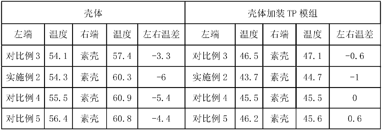
[0041] The heat-conducting paint is sprayed onto the surface of the left side of the upper casing of the mobile phone by means of electrostatic spraying.

Embodiment 3

[0043] This embodiment provides a processing method for a terminal device housing, including:

[0044] Water-based polyurethane resin, surfactant, graphite, metal copper particles and deionized water are according to the mass parts of 30 parts of water-based polyurethane resin, 0.5 parts of surfactant, 8 parts of graphite, 60 parts of deionized water and 14 parts of metal copper particles Mix evenly to form a thermally conductive coating;

[0045] The heat-conducting paint is sprayed onto the surfaces of the upper and lower casings of the mobile phone by means of electrostatic spraying.


PUM

PropertyMeasurementUnit
Thermal conductivityaaaaaaaaaa
Particle sizeaaaaaaaaaa
Thicknessaaaaaaaaaa

Abstract

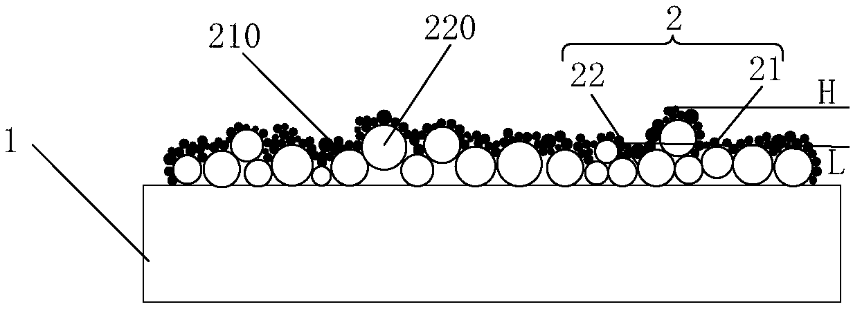
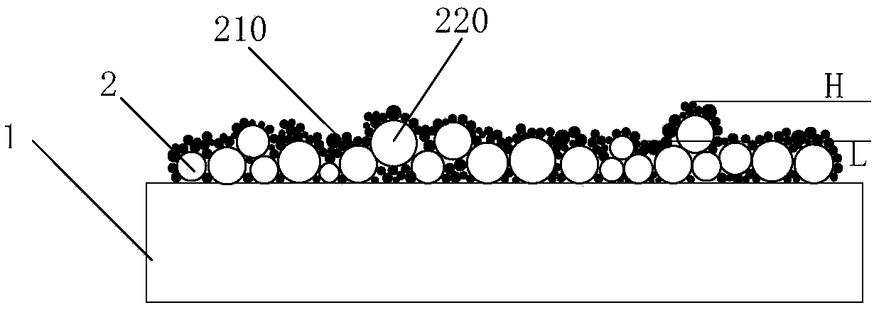
The invention provides a shell of terminal equipment and a processing method of the shell. The shell comprises a shell body and a heat conduction layer sprayed on a surface of the shell body, whereinnano carbon particles and heat conduction metal particles are contained in the heat conduction layer, and a surface of the heat conduction layer is provided with an uneven heat dissipation microstructure. The nano carbon particles have excellent heat conduction and heat radiation performance, the heat conduction performance is mainly reflected in heat diffusion transfer, the heat diffusion speed of the nano carbon particles is larger than or equal to 200 mm<2> / S, a heat radiation coefficient is 0.92-0.95, the nano carbon particles have excellent heat conduction performance, moreover, the carbon nanoparticles can form a continuous heat conduction channel on the surface of the shell after being dried, so heat conduction performance can be enhanced, and the heat can be conducted out more quickly. The particle size of the heat conduction metal particles is large, the nano carbon particles and the heat conduction metal particles can form the uneven heat dissipation microstructure on the surface of the shell body, the heat radiation area can be increased, and thereby heat dissipation performance of the heat conduction layer is further improved.

Description

technical field [0001] The present disclosure relates to the technical field of heat dissipation, and in particular to a housing of a terminal device and a processing method thereof. Background technique [0002] At present, the emergence of large-scale integrated circuits has promoted the development of the intelligent terminal industry. At the same time, the increasing density of electronic components, the thinning of smart terminals and the compactness of packaging technology have made effective thermal management very difficult, and local overheating problems will occur when smart terminals work for a long time. [0003] At present, the common heat dissipation methods include attaching heat dissipation film, thermal silica gel and copper plating, etc. Among them, the method of copper plating can form a dense and smooth copper layer on the terminal shell, which has good thermal conductivity and It can be closely attached to the terminal shell, thereby promoting the heat ...

Claims


Application Information

Patent Timeline
IPC IPC(8): H05K7/20
CPCH05K7/2039
Inventor 杨善强张新服
Owner QINGDAO HISENSE MOBILE COMM TECH CO LTD
Learn More