Array type jet flow water purifier

A water purifier, array type technology, applied in the direction of water/sewage treatment, chemical instruments and methods, water/sewage treatment equipment, etc., can solve the problems of slow purification rate, poor diffusivity, easy corrosion and failure of electrodes, and achieve convenience Overhaul, improve purification efficiency, and improve the effect of purification flow

Active Publication Date: 2020-01-03
DALIAN NATIONALITIES UNIVERSITY
View PDF6 Cites 2 Cited by
  • Summary
  • Abstract
  • Description
  • Claims
  • Application Information

AI Technical Summary

Problems solved by technology

[0004] In view of the problems in the prior art that the purification rate of the non-equilibrium plasma technology is too slow, the electrode is easy to corrode and fail, the needle electrode corona discharge is easy to wear, and the diffusivity is poor, the application proposes an array jet water purifier

Method used


Image

  • Array type jet flow water purifier
  • Array type jet flow water purifier

Examples


Embodiment 1

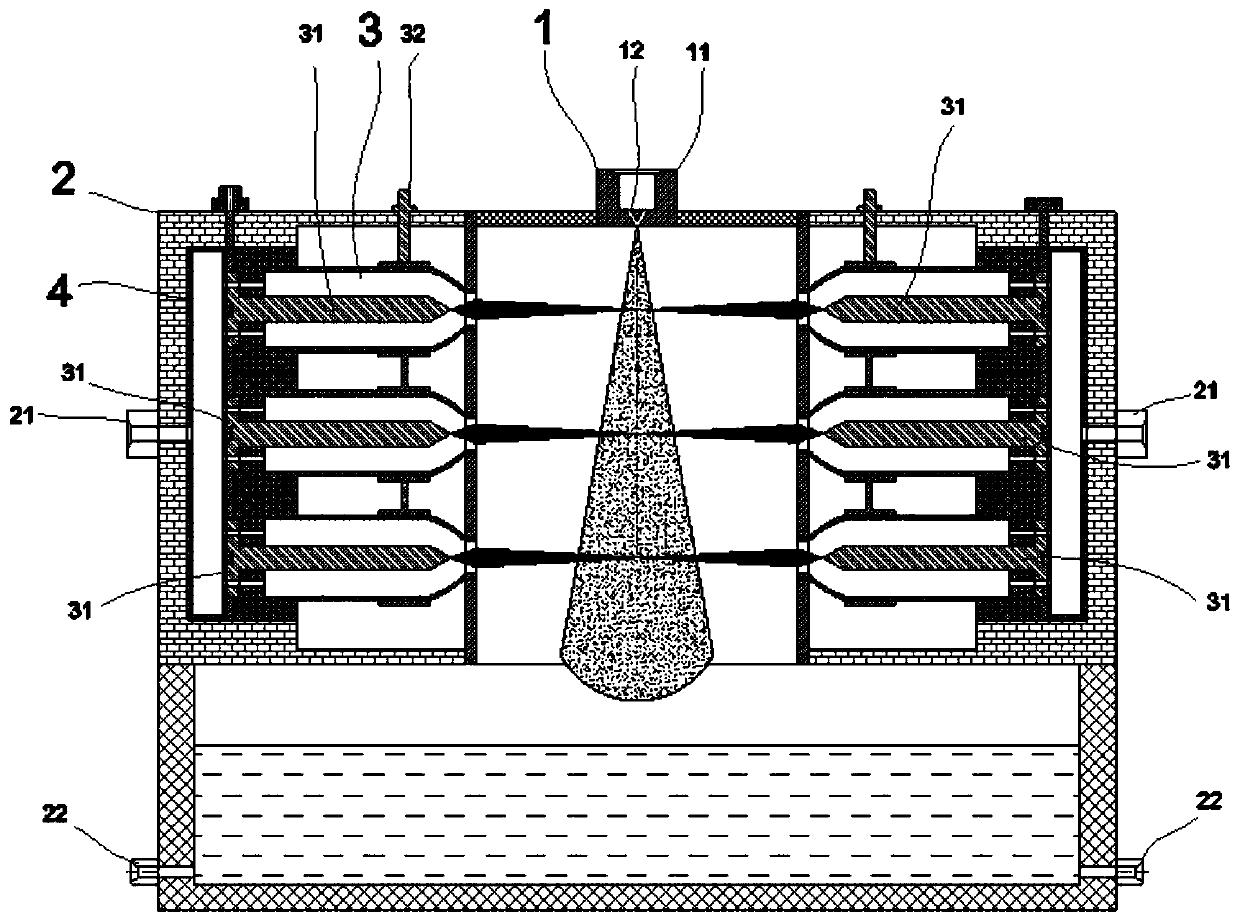
[0021] This embodiment provides an array jet water purifier, comprising: a liquid atomizer, a purifier frame, an unbalanced plasma jet exciter, an air intake stabilizing chamber and a purified water tank, and a purifier is arranged on the purified water tank frame body, a first baffle plate and a second baffle plate are arranged in the purifier frame body, and a multi-layer unbalanced plasma jet exciter is arranged between the first baffle plate and the second baffle plate, and the multiple layers of each layer The two unbalanced plasma jet exciters are distributed in a circle; the area between the first baffle plate and the inner wall of the purifier frame is an air intake plenum, and an air inlet is processed on the purifier frame, and the second A jet port is processed on the baffle, one end of the unbalanced plasma jet actuator is fixed on the first baffle, and the other end of the unbalanced plasma jet actuator is an ejection port, and the ejection port is aligned with the...

Embodiment 2

[0028] This embodiment provides a working method of an array jet water purifier, comprising the following steps:

[0029] 1. The plasma power supply supplies power to the high-voltage electrode, and forms an electric field in the space between the high-voltage electrode and the ground electrode;

[0030] 2. The valve opening electronic controller controls the gas flow control valve to open, and the high-pressure gas in the high-pressure gas cylinder enters the electric field space to form a plasma jet and eject it. A plurality of circumferentially distributed plasma jet exciters are arranged on each layer, so that the distribution area of ​​the ejected unbalanced plasma jet is relatively large, and the liquid spray atomized by the liquid atomizer can be completely covered. Multiple layers of circumferentially distributed plasma jet actuators are provided to make the treatment more adequate.

[0031] 3. The valve opening electronic controller controls the opening of the liquid...


PUM


Abstract

The invention discloses an array type jet flow water purifier. A purifier frame body is arranged on a purification water tank, a first baffle plate and a second baffle plate are arranged in the purifier frame body, multiple layers of non-equilibrium plasma jet flow exciters are arranged between the first baffle plate and the second baffle plate, and the multiple non-equilibrium plasma jet flow exciters of each layer are distributed circumferentially; the area between the first baffle plate and the inner wall of the purifier frame body is an air inflow pressure stabilizing cavity, air inlets are formed in the purifier frame body, jet orifices are formed in the second baffle plate, one end of each non-equilibrium plasma jet flow exciter is fixed on the first baffle plate, and spray nozzles are arranged the other ends of the non-equilibrium plasma jet flow exciters and aligned to the corresponding jet orifices; and an internal area defined by the second baffle plate is a purification area. With the adoption of the technical scheme of the liquid atomization technology and the non-equilibrium plasma jet flow technology, the purification efficiency can be substantially increased, and thepurification flow rate can also be greatly increased.

Description

technical field [0001] The invention relates to a purification device, in particular to an array jet water purifier. Background technique [0002] When non-equilibrium plasma technology is used to treat domestic sewage, medical wastewater, industrial wastewater, ship ballast water and other wastewater, the liquid flow rate is too small due to the too small size of the ionization space (that is, the aperture of the liquid flow channel), which easily leads to an excessive purification rate. slow; moreover, because all the substances to be treated are in liquid phase, it is easy to cause non-equilibrium plasma discharge failure, resulting in purification failure; moreover, in the existing plasma water purification technology, the sewage flows through the plasma electrode space, which is bound to contact with the electrode. This will cause corrosion and failure of the electrodes. [0003] In the prior art, Chinese utility model patent application number: 200720013297.0, name: a...

Claims


Application Information

Patent Timeline
Patent Type & Authority Applications(China)
IPC IPC(8): C02F1/46
CPCC02F1/4608C02F2201/002C02F2303/14C02F2303/04Y02A50/20
Inventor 宋鹏
Owner DALIAN NATIONALITIES UNIVERSITY
Why Eureka
Try Eureka