Biomass oil-gas co-production device and method based on chemical chain

A biomass and chemical chain technology, which is applied in the fields of biofuel, gasification process, petroleum industry, etc., can solve the problems of gasification gas production cost increase, waste, water resource waste energy, etc., to achieve self-heat balance and ensure full Effects of pyrolysis, enhanced contact and heat conduction

Pending Publication Date: 2020-01-03
SOUTH CHINA UNIV OF TECH
View PDF0 Cites 4 Cited by
  • Summary
  • Abstract
  • Description
  • Claims
  • Application Information

AI Technical Summary

Problems solved by technology

In order to obtain qualified biomass gas, most of the existing processes use water washing or secondary cracking to reduce the tar in the gas, resulting in a lot of waste of water resources and energy contained in the tar, or adding a catalyst for secondary pyrolysis Causes an increase in the production cost of gasification gas

Method used


Image

  • Biomass oil-gas co-production device and method based on chemical chain

Examples


Embodiment 1

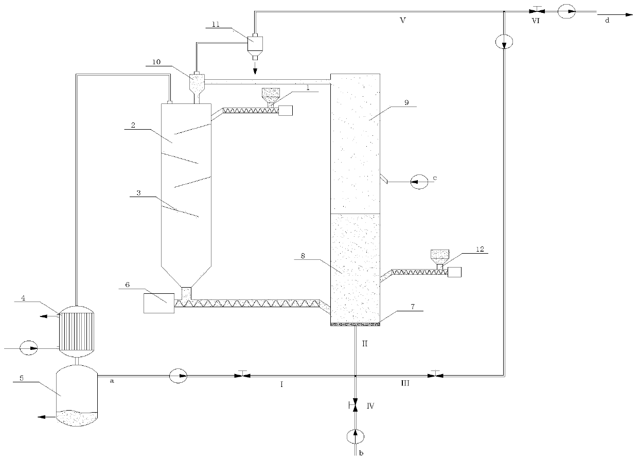
[0065] A certain amount of oxygen carrier particles (Ca 2 Fe 2 o 5 ) into the fuel reaction chamber 8 as bed material, and the bed material is preheated to 800°C. Turn on the steam generator, wait for the water vapor to fill the entire oxidation reaction chamber 9 and keep it stable, open the fluidizing gas valve to make the oxygen carrier particles circulate stably between the pyrolysis reactor 2 and the gasification reactor, by adjusting the flow rate of the fluidizing gas Control the temperature of pyrolysis reactor 2 to maintain at 450°C all the time. The biomass raw material (rice straw) enters the pyrolysis reactor 2 from the first screw feeder 1, and under the action of the baffle plate 3, the biomass is fully mixed with the oxygen carrier and undergoes pyrolysis reaction. The reacted solid product is sent to the fuel reaction chamber 8 through the screw feeder 6, and the pyrolysis gas pipeline I and the fluidization gas CO are not condensed at the same time. 2 The ...

Embodiment 2

[0067] A certain amount of oxygen carrier particles (Ca 2 Fe 2 o 5 / MgO) is charged into the fuel reaction chamber 8 as bed material, and the bed material is preheated to 850°C. Turn on the steam generator, wait for the water vapor to fill the entire oxidation reaction chamber 9 and keep it stable, open the fluidizing gas valve to make the oxygen carrier particles circulate stably between the pyrolysis reactor 2 and the gasification reactor, by adjusting the flow rate of the fluidizing gas Control the temperature of pyrolysis reactor 2 to maintain at 480°C all the time. The biomass raw material (cotton stalk) enters the pyrolysis reactor 2 from the first screw feeder 1 , and under the action of the baffle plate 3 , the biomass is fully mixed with the oxygen carrier and undergoes pyrolysis reaction. The reacted solid product is sent to the fuel reaction chamber 8 through the screw feeder 6, and the pyrolysis gas pipeline I and the fluidization gas CO are not condensed at the...


PUM


Abstract

The invention discloses a biomass oil-gas co-production device and method based on a chemical chain. The device comprises a pyrolyzing furnace, a chemical-looping gasification reactor and a condensingdevice, a first cyclone separator is arranged at the top of the pyrolyzing furnace; the side surface of a fuel reaction chamber is communicated with a second spiral feeder, the bottom is provided with a fluidization gas pipeline inlet, the side surface of an oxidation reaction chamber is connected with an oxidation gas pipeline inlet, and the top is connected with the first cyclone separator; biomass and an oxygen carrier are subjected to a pyrolysis reaction in a pyrolysis reactor; after pyrolysis gas is cooled by the condensing device, bio-oil is stored in an oil storage tank, and meanwhile, a non-condensable gas is exhausted; a solid product enters the fuel reaction chamber to be gasified, after reaction, the product enters the oxidation reaction chamber under the action of fluidized gas, a hydrogen-rich gasified gas is generated under the oxidation condition of water vapor, and meanwhile, the oxygen carrier enters the pyrolysis reactor again through gas-solid separation. Accordingto the device and method, the biomass is adopted as a raw material, the bio-oil and the gasified gas are prepared at the same time through gradient utilization, and the utilization quality of the biomass is improved.

Description

technical field [0001] The invention relates to the fields of chemical engineering and energy utilization of biomass oil and gas cogeneration, in particular to a chemical chain-based biomass oil and gas cogeneration device and method. Background technique [0002] Biomass, which is abundant and easy to obtain, is an important fuel that can replace fossil energy. Its development and utilization are of great significance for alleviating energy shortage and environmental pollution. The preparation of high-grade fuels such as bio-fuel and syngas through biomass pyrolysis and gasification processes is conducive to improving the high-quality utilization of biomass. [0003] Biomass pyrolysis is a complex physical and chemical process that forms three products by cracking hydrocarbons in biomass: liquid (bio-oil), solid (coke), and gas (combustible gas). The traditional pyrolysis technology realizes the thermal cracking of all components of biomass in an inert atmosphere, medium t...

Claims


Application Information

Patent Timeline
Patent Type & Authority Applications(China)
IPC IPC(8): C10B53/02C10B43/00C10J3/56C10J3/72
CPCC10B43/00C10B53/02C10J3/56C10J3/72C10J2300/0916Y02E50/10
Inventor 廖艳芬莫菲马晓茜刘桂才
Owner SOUTH CHINA UNIV OF TECH
Why Eureka
Try Eureka