
Orbital angular momentum mode multiplexing and demultiplexing coupler based on microstructure optical fiber

A technology of orbital angular momentum and microstructure optical fiber, which is applied in the field of orbital angular momentum mode multiplexing and demultiplexing couplers, which can solve the problems of large insertion loss, unfavorable integration, and increased difficulty in making photon lanterns, achieving low loss and flexible design , the effect of simple structure

Active Publication Date: 2020-01-10
NANKAI UNIV
View PDF6 Cites 11 Cited by
  • Summary
  • Abstract
  • Description
  • Claims
  • Application Information

AI Technical Summary

Problems solved by technology

[0004] The technical problem to be solved by the present invention: the orbital angular momentum mode multiplexer based on the long-period fiber grating and the mode selection coupler needs a high-level In view of the current situation that multiple devices are connected, and the difficulty of making photonic lanterns increases with the number of multiplexing modes, a microstructured optical fiber-based orbital angular momentum mode multiplexing and demultiplexing coupler is proposed.

Method used


Image

  • Orbital angular momentum mode multiplexing and demultiplexing coupler based on microstructure optical fiber
  • Orbital angular momentum mode multiplexing and demultiplexing coupler based on microstructure optical fiber
  • Orbital angular momentum mode multiplexing and demultiplexing coupler based on microstructure optical fiber

Examples


Embodiment Construction

[0021] Below in conjunction with the accompanying drawings, the present invention will be further described by taking the design of an OAM mode-division multiplexing coupler that realizes multiplexing of 4 OAM modules and 16 OAM modes based on a microstructure optical fiber as an example. The accompanying drawings are only for illustrative purposes, and It is not intended to limit the scope of applicability of the present invention.

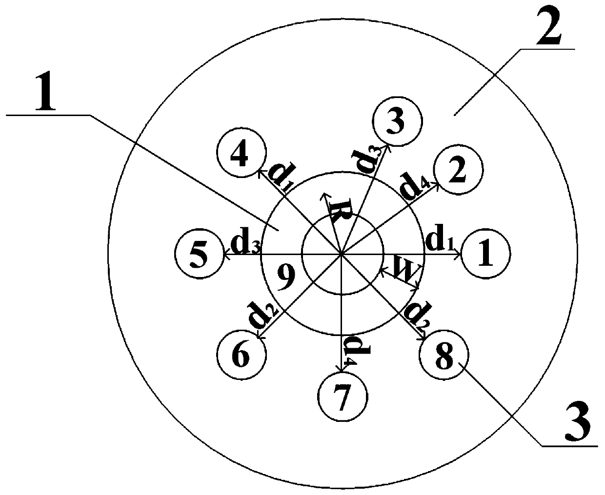
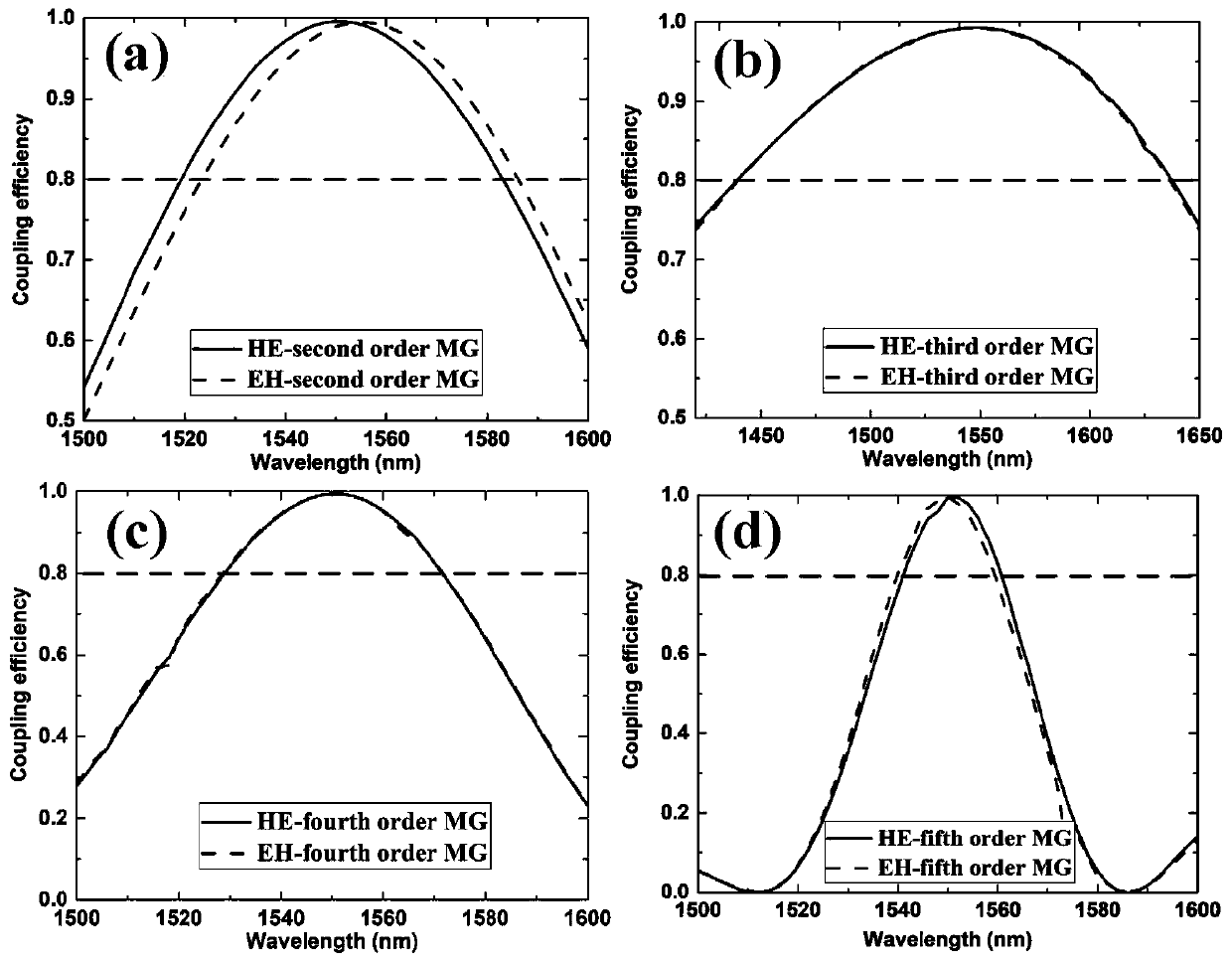
[0022] like figure 1 and 2 As shown in the figure, the orbital angular momentum mode multiplexing and demultiplexing coupler based on microstructured fiber includes an intermediate annular core (1) that supports the transmission of N orbital angular momentum modes in a band with a given central wavelength of λ (1), a background The material (2) and n single-mode fiber cores (3) that only support fundamental mode transmission, where n=2N, and in the embodiment of the present invention, N=4 and n=8. The process of determining the parameters of th...


PUM


Abstract

The invention discloses an orbital angular momentum mode multiplexing and demultiplexing coupler based on a microstructure optical fiber. The orbital angular momentum mode multiplexing and demultiplexing coupler comprises a middle annular fiber core which supports N orbital angular momentum mode transmission in a waveband with a given central wavelength lambda, a background material, and n single-mode fiber cores which only support fundamental mode transmission and are distributed around the annular fiber core, n=2N, and the single-mode fiber cores are divided into N pairs. The refractive indexes of the single-mode fiber cores and the annular fiber core are higher than that of the background material. The radiuses of the two single-mode fiber cores in each pair of single-mode fiber cores,refractive index differences between the two single-mode fiber cores and the background material and distances between the two single-mode fiber cores and the annular fiber core are equal, included angles between the two single-mode fiber cores and a center of the coupler is (2m + 1) pi / 2l, m = 0, 1, 2...(l1), and l is orders of orbital angular momentum modes of the single-mode fiber cores coupledto middle annular fiber core. According to the orbital angular momentum mode multiplexing and demultiplexing coupler, N pairs of single-mode signals in the single-mode fiber cores are multiplexed toN orbital angular momentum modes in the middle annular fiber core, the mode division multiplexing is realized, and so the transmission capacity of an optical fiber communication system is increased.

Description

technical field [0001] The invention relates to an orbital angular momentum mode multiplexing and demultiplexing coupler based on a microstructure optical fiber, which is used for realizing multiplexing of multiple orbital angular momentum modes and has important application value in a space division multiplexing transmission system. Background technique [0002] In recent years, bandwidth-consuming services such as mobile Internet, Internet of Things, and cloud computing data centers have been increasing, posing huge challenges to existing communication systems. Therefore, how to continuously improve the capacity of the communication system to meet the ever-increasing demand for communication capacity has become an urgent problem to be solved in optical communication. In recent years, the methods to solve this problem mainly include multiplexing technologies such as wavelength division multiplexing, time division multiplexing, offset division multiplexing, and orthogonal fr...

Claims


Application Information

Patent Timeline
Patent Type & Authority Applications(China)
IPC IPC(8): G02B6/28
CPCG02B6/2804
Inventor 刘艳格张红伟郭慧毅毛百威王志刘波张昊
Owner NANKAI UNIV
Learn More