
Casting system and method for frame

A pouring system and rack technology, which is applied to equipment for feeding molten metal into molds, casting molding equipment, molds, etc. Improve the complete pass rate and reduce the effect of scouring

Pending Publication Date: 2020-01-17
ANQING CSSC DIESEL ENGINE
View PDF0 Cites 1 Cited by
  • Summary
  • Abstract
  • Description
  • Claims
  • Application Information

AI Technical Summary

Problems solved by technology

[0011] The technical problem to be solved by the present invention is: how to solve the problem of poor casting quality caused by the characteristics of the existing pouring system, such as excessively fast molten iron flow rate and easy splashing

Method used


Image

  • Casting system and method for frame
  • Casting system and method for frame
  • Casting system and method for frame

Examples


Embodiment 1

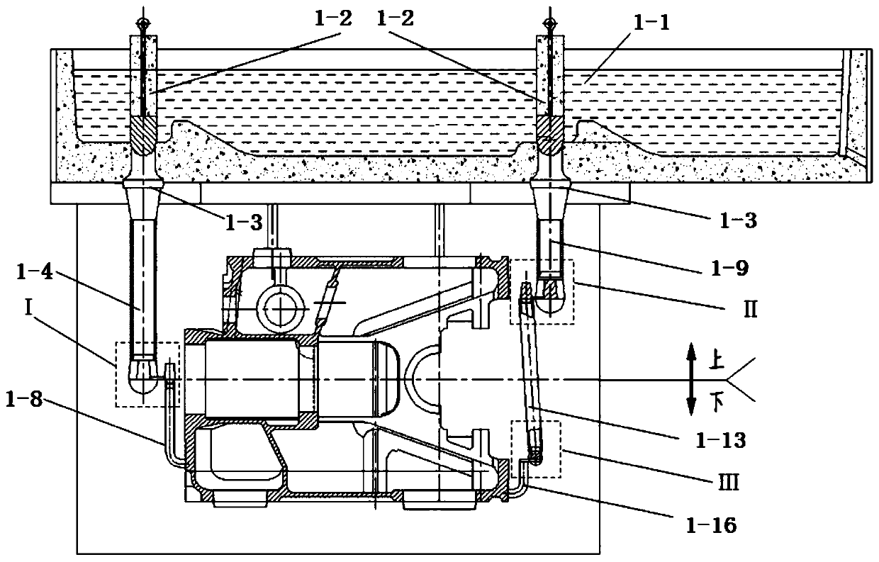
[0039] Such as figure 2 As shown, the gating system of the frame includes a first sprue 2, a first runner 3, two second sprues 4, two second runners 5, a plurality of filter units 6, a plurality of The inner runner 7, the first sprue 2 communicates with the upper part of the first runner 3, the lower part of the first runner 3 communicates with the two second runners 4 respectively, and the second sprue 4 communicates with the first runner 4. The upper part of the two runners 5 communicates, and each second runner 5 is provided with a filter unit 6 communicating with it, and the inrunner 7 communicates with the filter unit 6; during pouring, in the mold cavity, the exhaust side of the frame faces Down, the operating side faces up, the gating system is introduced from one side of the oil pan side, and the molten iron enters from the bottom of the cavity of the casting frame through the inrunner.

[0040] Wherein, the upper part of the first sprue 2 is also provided with a spru...

Embodiment 2

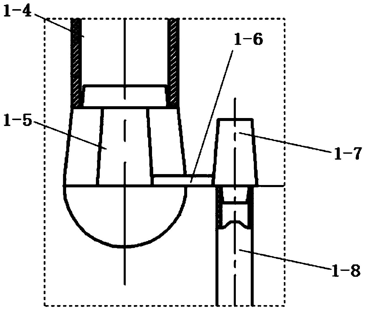
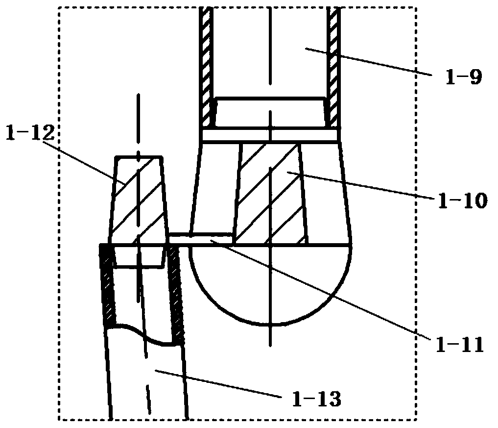
[0042] Such as image 3 As shown, the filter unit 6 in the present embodiment includes a filter cavity 61, the filter cavity 61 is provided with an inverted trapezoidal structure, and has the effect of gathering and collecting, and the filter sheet 62 is laterally fixed on the large mouth end of the filter cavity 61 for filtering from the first The pouring liquid of the second horizontal runner 5, the filter 61 is a foam ceramic filter, and the foam ceramic filter can choose silicon carbide, corundum and other different refractory materials and specifications according to the needs. In this embodiment, a square structure is adopted. Moreover, two adjacent filter chambers 61 share one filter sheet 62 , or separate filter sheets may be used respectively.

[0043] Wherein, the number of the filter unit 6 is the same as that of the inrunner 7, so as to ensure that the pouring liquid is all filtered.

[0044]In this embodiment, there are two second runners 5, and 16 filter units, ...


PUM


Abstract

The invention provides a casting system for a frame. The casting system comprises a first sprue, a first runner, one or more second sprues, one or more second runners, a plurality of filtering units and a plurality of ingates, wherein the first sprue communicates with the upper part of the first runner; the lower part of the first runner communicates with the one or more second sprues; the secondsprues communicate with the upper parts of the second runners; the filtering units communicating with the corresponding second runners are arranged at the lower parts of the corresponding second runners; and the ingates communicate with the filtering units. The invention also discloses a casting method for the frame. A horizontal moulding and pouring process is adopted, an exhaust side surface faces downwards, an operation side faces upwards, the casting system is introduced from a single side of an oil sump side, and molten iron enters from the bottom to realize a pure bottom casting type casting way. The casting system and the casting method have the beneficial effects that the operation is simple, the yield is high, and the stability is high; and defects of shrinkage porosity, air holesand slag holes of a frame casting are effectively reduced, the quality loss is reduced, and the fully-qualified rate of the casting is greatly increased.

Description

technical field [0001] The invention relates to a pouring system and method, in particular to a pouring system and method for a frame. Background technique [0002] The frame is one of the most important parts of the marine diesel engine frame. As the installation matrix of almost all parts of the diesel engine, it is often in a state of complex stress and variable load during work. Therefore, for frame castings, good strength, toughness , impact resistance and other mechanical properties are essential, especially for the compactness of the internal matrix structure of the casting; this targeted casting process meets the increasing strengthening degree (PeCm) of the diesel engine frame and mass production requirements. [0003] The original pouring system technology adopts the bridge type to introduce molten metal from the side of the cylinder hole and the claw side of the foot plate respectively. The flow rate of molten iron is reduced by designing a choke channel, and the...

Claims


Application Information

Patent Timeline
IPC IPC(8): B22C9/08B22D35/04
CPCB22C9/082B22C9/086B22D35/045
Inventor 王刚钱维胡发林王涛
Owner ANQING CSSC DIESEL ENGINE
Features
  • Generate Ideas
  • Intellectual Property
  • Life Sciences
  • Materials
  • Tech Scout
  • Unparalleled Data Quality
  • Higher Quality Content
  • 60% Fewer Hallucinations
Learn More