
Multifunctional automatic simulation test device for top corrosion of moisture pipeline

A simulated test and multi-functional technology, applied in weather resistance/light resistance/corrosion resistance, measuring devices, instruments, etc., can solve problems such as difficulty in effectively protecting the top, corrosion of the top of the pipeline, and potential safety hazards

Active Publication Date: 2020-01-17
XI'AN PETROLEUM UNIVERSITY
View PDF7 Cites 8 Cited by
  • Summary
  • Abstract
  • Description
  • Claims
  • Application Information

AI Technical Summary

Problems solved by technology

At present, the understanding of top corrosion is not sufficient. Conventional corrosion inhibitors are difficult to effectively protect the top. The problem of pipe top corrosion is becoming more and more serious, especially pitting corrosion. The corrosion rate of the wedge-shaped pits on the top of the pipe is even as high as 5mm / a
In addition, although some pipes are coated with coatings, they are partially damaged due to some reasons, forming a "big cathode-small anode", which further aggravates pitting corrosion
Pitting corrosion is difficult to monitor and predict, and the risks and hazards caused by it are huge
Once the oil pipe is perforated, it will not only reduce the oil and gas production capacity, shorten the pipeline replacement cycle, increase the maintenance cost, and most importantly, it will also cause safety hazards to the field personnel in the oil and gas field, and the leaked oil and gas will also pollute the gas, soil and water , causing environmental risks

Method used


Image

  • Multifunctional automatic simulation test device for top corrosion of moisture pipeline
  • Multifunctional automatic simulation test device for top corrosion of moisture pipeline

Examples


Embodiment Construction

[0033] The present invention will be specifically introduced below in conjunction with the accompanying drawings and specific embodiments.

[0034] 1. The composition of the automatic simulation test device

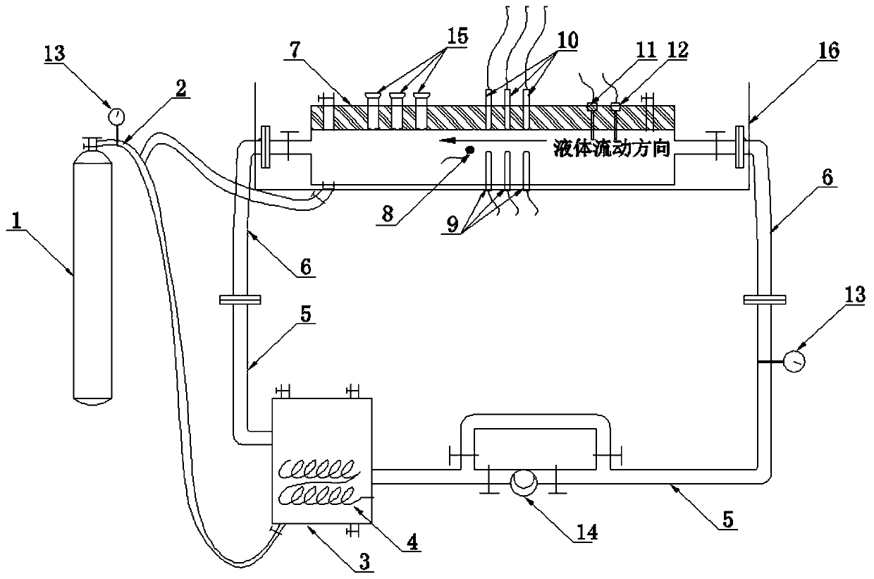
[0035] The multifunctional wet gas pipeline top corrosion automatic simulation test device provided by the invention is composed of two major systems, which are respectively: a test loop system and a control and display system.

[0036] 1. Test loop system

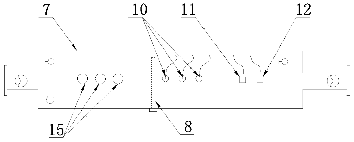
[0037] refer to figure 1 , The test loop system includes: gas cylinder 1, gas hose 2, deposition tank 3, electric heater 4, fixed tube 5, flexible composite tube 6, test tube 7, auxiliary electrode 8, reference electrode 9, working electrode 10 , temperature probe 11, pressure probe 12, flow meter 13, flow pump 14 and constant temperature bath 16.

[0038]The sedimentation tank 3 is made of polytetrafluoroethylene, corrosion-resistant alloy or PVC, and is used to hold the test medium (simulated solution) and precip...


PUM


Abstract

The invention discloses a multifunctional automatic simulation test device for top corrosion of a moisture pipeline. The multifunctional automatic simulation test device is composed of a test loop system and a control and display system, wherein the test loop system comprises a gas cylinder, a deposition tank, an electric heater, a fixed pipe, flexible composite pipes, a test pipe, electrodes, a temperature probe, a pressure probe and the like; the test pipe is a rectangular square pipe; a gas injection opening and a plurality of reference electrode mounting holes are reserved in the bottom surface of the test pipe; a liquid injection opening, an exhausting opening, a plurality of sample mounting holes, a plurality of working electrode mounting holes and a probe mounting hole are reservedin the top surface of the test pipe; an auxiliary electrode mounting hole is reserved in the side face of the test pipe; and the two ends of the test pipe are each connected with one flexible composite pipe through a flange. The multifunctional automatic simulation test device disclosed by the invention has the beneficial effects that the device can reflect a condition of the top corrosion of themoisture pipeline paved at 0-90 degrees in an oil gas development process, and can also evaluate the efficiency of a corrosion inhibitor under a working condition and the corrosion reduction effect ofthe corrosion inhibitor on a local damaged part of a coating.

Description

technical field [0001] The invention relates to a test device, in particular to a multifunctional wet gas pipeline top corrosion automatic simulation test device, which belongs to the technical field of oil and gas field development. Background technique [0002] With the extension of the production life of oil and gas wells, the water content in the produced fluid increases year by year, which in turn increases the erosion of metal pipes. [0003] In recent years, in order to further enhance oil recovery, water injection or CO 2 - Alternate injection of water to recover crude oil, reducing CO in coal chemical industry and hydrogen production industry in the future 2 While exhausting, it can also increase CO 2 The swept area of ​​flooding and the increase of crude oil recovery, but this will further increase the water cut in the produced fluid and the CO 2 content. At the same time, the fluids produced during oil and gas development usually contain different degrees of c...

Claims


Application Information

Patent Timeline
Patent Type & Authority Applications(China)
IPC IPC(8): G01N17/00
CPCG01N17/006
Inventor 李金灵朱世东屈撑囤陈刚鱼涛杨博
Owner XI'AN PETROLEUM UNIVERSITY
Learn More