
Non-destructive testing equipment and method for directed energy deposition process based on coherent imaging

A technology of energy deposition and non-destructive testing, which is applied in measuring devices, optical testing of flaws/defects, and material analysis through optical means. It can solve problems such as detection blind spots, missed parts inspection, and radiographic opacity, so as to reduce waste products. The effect of high efficiency, cost reduction and simple process

Active Publication Date: 2021-02-05
HUAZHONG UNIV OF SCI & TECH
View PDF2 Cites 0 Cited by
  • Summary
  • Abstract
  • Description
  • Claims
  • Application Information

AI Technical Summary

Problems solved by technology

On the one hand, due to the complexity of the part structure, there will be detection blind spots in the overall inspection, such as radiopaque caused by overlapping structures, skin effect and edge effect of eddy current, etc., which cause parts to be missed; on the other hand, once the inspection finds that there are defects inside the workpiece , the existing repair welding, milling and other methods cannot repair internal defects. Therefore, strengthening quality control, detecting and processing defects in real time, and avoiding waste products in completion inspection are urgent problems that need to be solved in current arc deposition additive manufacturing.

Method used


Image

  • Non-destructive testing equipment and method for directed energy deposition process based on coherent imaging
  • Non-destructive testing equipment and method for directed energy deposition process based on coherent imaging
  • Non-destructive testing equipment and method for directed energy deposition process based on coherent imaging

Examples


Embodiment 1

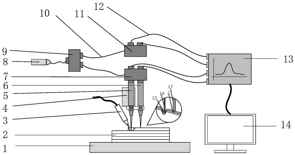
[0042] The heat source used by the coherent imaging-based directed energy deposition process non-destructive testing equipment provided by the first embodiment of the present invention is an arc heat source, the directed energy deposition method is MIG welding, and the heat source is fixedly connected with the testing equipment to a moving mechanism Above, the motion mechanism moves from right to left and from bottom to top, realizing layer-by-layer 3D printing.

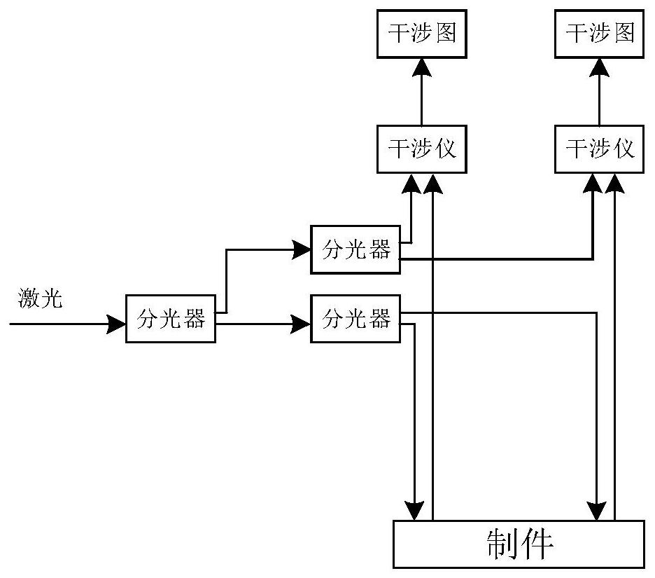
[0043] The laser light of the detection device is emitted from the pulse laser, and the detection light A and the detection light B are obtained through the first optical splitter and the second optical splitter; the reference light A and the reference light B are obtained through the first optical splitter and the third optical splitter .


PUM


Abstract

The invention belongs to the technical field related to metal additive manufacturing, and discloses a nondestructive testing device and method for a directional energy deposition process based on coherent imaging. The device includes a first beam splitter, a laser generator, a second beam splitter, and a third beam splitter , interferometer and host computer system, the laser generator is connected to the second beam splitter, the third beam splitter is connected to the first beam splitter and the second beam splitter respectively, and the first beam splitter and the third beam splitter are respectively connected to the interference The interferometer is connected to the host computer system. The upper computer system is used to process the received first interferogram and second interferogram to obtain the molten pool depth variation curve, molten pool height variation curve and molten pool width variation curve, and then the internal pore defects and surface defects of the parts to be inspected Real-time detection is carried out, thereby realizing in-situ online non-destructive detection of internal pore defects and surface defects during the directed energy deposition process. The invention realizes real-time detection and has better flexibility.

Description

technical field [0001] The invention belongs to the technical field related to metal additive manufacturing, and more specifically relates to a nondestructive testing device and method for a directed energy deposition process based on coherent imaging. Background technique [0002] The metal additive manufacturing process is a multi-physics coupling process. There are various unstable factors in the forming process, the temperature changes drastically, the solidification rate of the molten pool is large, and the formed parts are prone to macroscopic defects such as weld bead offset, hump, and flow. Defects, unpredictable metallurgical defects such as cracks, pores, and slag inclusions are prone to appear inside the parts. Small defects such as pores gradually expand under the long-term action of alternating stress, which may eventually cause fatigue fracture accidents, especially in the field of aerospace, once fatigue fracture accidents of important components occur, it wil...

Claims


Application Information

Patent Timeline
Patent Type & Authority Patents(China)
IPC IPC(8): G01N21/88G01N21/01
CPCG01N21/01G01N21/88G01N2021/0112
Inventor 张海鸥陈曦宋豪唐尚勇王桂兰
Owner HUAZHONG UNIV OF SCI & TECH
Learn More