Laser cutting device and laser cutting work method

A laser cutting and equipment technology, applied in laser welding equipment, welding equipment, metal processing equipment, etc., can solve the problems of affecting production rhythm, positioning accuracy, unqualified cutting hole quality, etc., to ensure continuous and stable production and cutting accuracy. high effect

Active Publication Date: 2020-01-21
WUHAN FARLEYLASERLAB CUTTING SYST ENG
View PDF6 Cites 4 Cited by
  • Summary
  • Abstract
  • Description
  • Claims
  • Application Information

AI Technical Summary

Problems solved by technology

Of course, there are also two holes punched out by stamping equipment on the assembly line. This processing method can ensure the relative positional relationship, but the positioning accuracy of the two holes themselves will also be affected by the manufacturing deviation of the car body.
In addition, worn punching heads are often replaced during online punching. This will increase the cost and affect the production cycle.
In addition, in the process of completing the hole cutting process in the above method, the quality of the cutting hole will be unqualified due to the wear of the cutter head or the failure to replace the worn cutter head in time. However, there is no quality judgment mechanism for the hole cutting in the above method, resulting in unqualified cut holes It flows into the next process, affecting the implementation of the next process and the quality of the whole vehicle

Method used


Image

  • Laser cutting device and laser cutting work method
  • Laser cutting device and laser cutting work method
  • Laser cutting device and laser cutting work method

Examples


Embodiment 1

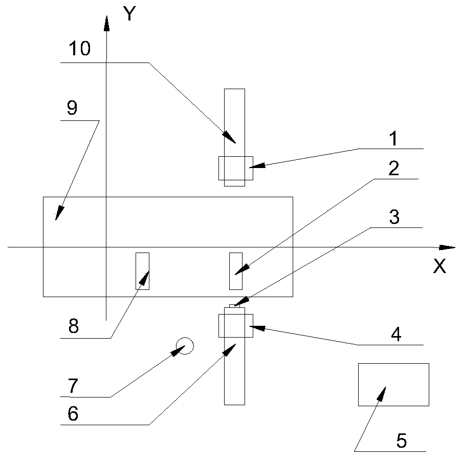
[0033] The laser cutting equipment in this embodiment is suitable for vehicle body processing, such as Figure 1-2 As shown, it includes: a cutting motion mechanism 6, in particular, the cutting motion mechanism 6 is a high-precision multi-axis motion system, and the repetitive motion accuracy is ≤0.05mm;

[0034] Laser cutting device 4, it is connected with described cutting motion mechanism 6, and produces the laser that is used for cutting; Laser cutting device 4 in the present embodiment is three-axis laser cutting cutting device, can finish 50mm in horizontal direction, height direction respectively. ≥10mm moving action, and can cut and form a cutting hole with a diameter of φ0.1mm; since laser cutting is a non-contact processing, it will not cause body vibration during the cutting process, and there is no consumption of the processing head, At the same time, the three-axis laser cutting device can also greatly improve the cutting accuracy, so that the cutting accuracy of...

Embodiment 2

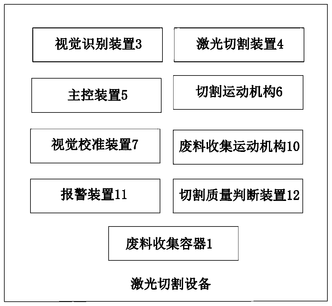
[0041] This embodiment still provides a kind of laser cutting equipment, and its only difference with Embodiment 1 is that, as figure 2 As shown, the laser cutting equipment in this embodiment also includes: a waste material collection motion mechanism 10, which is connected to the main control device 5; and a waste material collection container 1, which is connected to the waste material collection motion mechanism 10; and the waste material collection After receiving the vehicle type information, the motion mechanism 10 invokes the pre-stored waste collection movement path information corresponding to the vehicle type, and drives the waste collection container 1 to move to the vicinity of the cutting area according to the waste collection movement path information, so as to Complete collection of cutting waste.

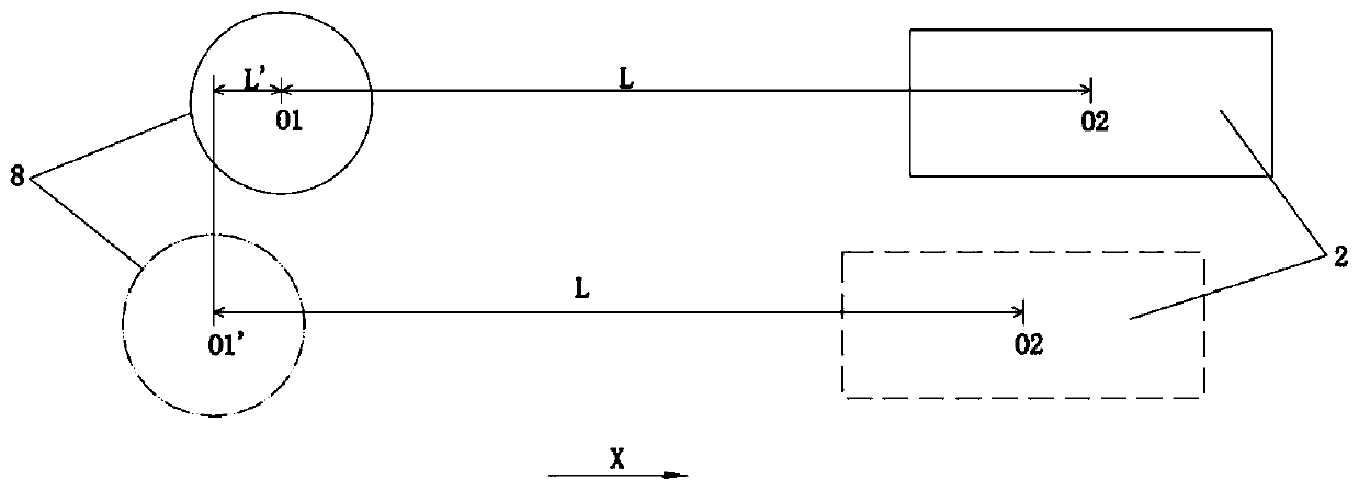
[0042] Similarly, the waste material collection motion mechanism 10 may also be a high-precision multi-axis motion system, and the waste material collection moveme...

Embodiment 3

[0046] This embodiment still provides a kind of laser cutting equipment, and its only difference with Embodiment 1 or 2 is that, as figure 2 As shown, the laser cutting equipment in this embodiment also includes: a cutting quality judging device 12, which is connected to the visual recognition device 3 and the alarm device, and is used to set the It is compared with the standard image information, and according to the comparison result, it is judged whether the hole and / or contour formed by cutting meets the quality standard, and a judgment result is formed, and the alarm device receives the judgment result, and generates an alarm signal when the judgment does not meet the quality standard; and The image information of the hole and / or contour formed by the cutting is obtained through the visual recognition device.

[0047] Therefore, by checking the cutting quality online after the cutting is completed, the cutting quality data can be obtained in time, fully ensuring the smoo...


PUM


Abstract

The invention relates to a laser cutting device and a laser cutting work method. The laser cutting device comprises a cutting movement mechanism, a laser cutting device, a visual recognition device and a master control device. The laser cutting device is connected with the cutting movement mechanism and generates lasers used for cutting. The visual recognition device is connected with the cuttingmovement mechanism and is used for obtaining image information of a specific structure on a vehicle body. The master control device is connected with the cutting movement device, the laser cutting device and the visual recognition device and is used for obtaining vehicle model information and controlling the laser cutting device to generate lasers used for cutting. The laser cutting device and thelaser cutting method are suitable for production of various vehicle models, the flexible degree is high, in addition, a cutting area can be accurately positioned, the machining precision is improved,the completion quality cutting work is detected online, and it is ensured that subsequent processes are implemented smoothly.

Description

technical field [0001] The invention relates to the technical field of laser cutting, in particular to a laser cutting device and a laser cutting operation method. Background technique [0002] There are many mounting holes and positioning holes in the processing of automobile body-in-white, which are usually formed by machining during the part blanking process. If only a single part is processed, the accuracy is relatively high. However, after installation on the body assembly line, with the cumulative deviation of the manufacturing size of the body and the corresponding deviation of the theoretical position of the single hole, the relative positional deviation of the two symmetrical holes will be very large, often up to ±3mm, which will bring great harm to the subsequent installation work. A lot of trouble. Of course, there are also two holes punched out by stamping equipment on the assembly line. This processing method can ensure the relative positional relationship, but...

Claims


Application Information

Patent Timeline
Patent Type & Authority Applications(China)
IPC IPC(8): B23K26/38B23K26/70
CPCB23K26/38B23K26/70B23K26/702
Inventor 沈义吴苶
Owner WUHAN FARLEYLASERLAB CUTTING SYST ENG
Why Eureka
Try Eureka