Aerobic composting waste heat power generation system and working method thereof

An aerobic composting and electrical system technology, applied in general control systems, control/regulation systems, fertilization devices, etc., can solve secondary pollution and other problems, achieve the effect of ensuring composting and preventing pollution of the surrounding environment

Pending Publication Date: 2020-01-21
SHANDONG UNIV
View PDF0 Cites 5 Cited by
  • Summary
  • Abstract
  • Description
  • Claims
  • Application Information

AI Technical Summary

Problems solved by technology

[0005] Aiming at the deficiencies of the prior art, the present invention provides an aerobic composting waste heat power generation system and its working method, so as to ensure that organic wastes can be processed and heat can be recovered from them at the same time, which solves the secondary pollution caused by excessive waste heat of traditional composting The problem

Method used


Image

  • Aerobic composting waste heat power generation system and working method thereof
  • Aerobic composting waste heat power generation system and working method thereof
  • Aerobic composting waste heat power generation system and working method thereof

Examples


Embodiment 1

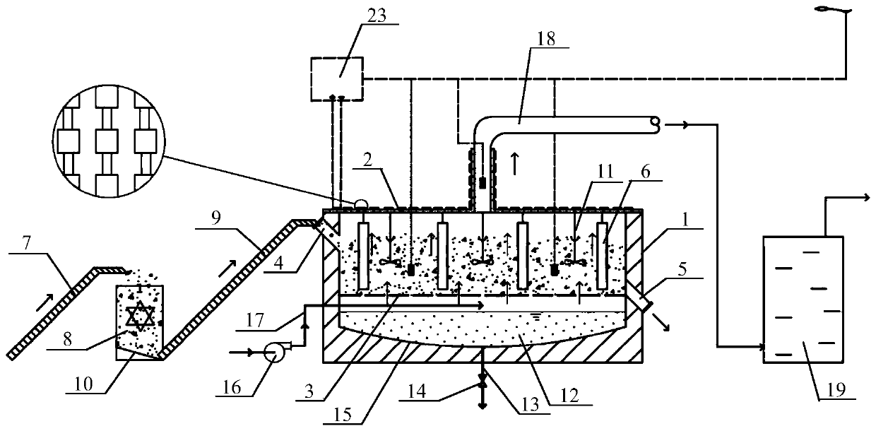
[0053] An aerobic compost waste heat power generation system, such as figure 1 As shown, it includes waste collection device, main composting reaction chamber 1, waste heat power generation device and exhaust gas collection device;

[0054] The surrounding and bottom of the main composting reaction chamber 1 are made of concrete pouring, and the top of the main composting reaction chamber 1 is provided with a heat conduction cover 2. The internal space of the main composting reaction chamber 1 includes an upper space and a lower space, and the upper space is a waste reactor. body, the lower space is a leachate collection device, a filter screen 3 is arranged between the upper space and the lower space, and a feed inlet 4 and an organic fertilizer outlet 5 are respectively arranged on the side wall of the upper space of the main composting reaction chamber 1. The composting reaction chamber 1 is also connected with an aeration device for aerating the reactor body;

[0055] The...

Embodiment 2

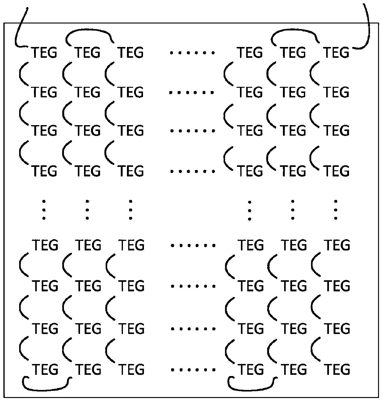
[0059] An aerobic composting waste heat power generation system, the structure of which is shown in Example 1, the difference is that the hot end side of the semiconductor thermoelectric power generation sheet is attached to the outer surface of the heat conduction cover 2, and the surface of the cold end side is installed with heat dissipation Better aluminum heat sink to ensure the temperature difference between the two sides of the temperature difference sheet.

Embodiment 3

[0061] An aerobic composting waste heat power generation system, its structure is as shown in Example 1, the difference is that the waste collection device includes a collection conveyor belt 7, a waste crushing and stirring device 8 and a feed conveyor belt 9, and the collection conveyor belt 7 adopts an inclined The upward transmission belt is realized, and its end is located directly above the waste crushing and stirring device 8. The discharge port of the waste crushing and stirring device 8 is connected to one end of the feeding conveyor belt 9, and the other end of the feeding conveyor belt 9 is connected to the main composting reaction chamber 1 The feeding port 4 is connected to transport the uniformly mixed waste to the main composting reaction chamber 1;

[0062] The bottom of the waste crushing and stirring device 8 is provided with a collection slope 10, and the collection slope 10 is inclined to the feed conveyor belt 9, that is, the lowest point of the collection ...


PUM

PropertyMeasurementUnit
thicknessaaaaaaaaaa
angleaaaaaaaaaa
thicknessaaaaaaaaaa

Abstract

The invention relates to an aerobic composting waste heat power generation system and a working method thereof, and belongs to the field of organic solid waste resource utilization. The system comprises a waste collection device, a main composting reaction chamber, a waste heat power generation device and a tail gas collection device, wherein a heat conduction cover is arranged at the top of the main composting reaction chamber, the upper space of the main composting reaction chamber is a waste reactor body, the lower space of the main composting reaction chamber is a leachate collection device, a filter screen is arranged between the upper space and the lower space, and the main composting reaction chamber is further connected with an aeration device; the bottom of the heat conduction cover is connected with the reactor body through a heat conduction rod; a waste heat power generation device is installed on the upper surface of the heat conduction cover and is formed by connecting a plurality of semiconductor thermoelectric power generation pieces in series, wherein the electric energy generated by the semiconductor thermoelectric power generation pieces is transmitted to an electricity storage and supply device. According to the invention, heat can be recovered from organic wastes while the organic wastes are treated, and the problem of secondary pollution caused by excessivewaste heat of traditional compost is solved.

Description

technical field [0001] The invention relates to an aerobic composting waste heat power generation system and a working method thereof, and belongs to the technical field of resource utilization of organic solid waste. Background technique [0002] In recent years, due to population growth and widespread urbanization, the problem of solid organic waste pollution has become a major obstacle on the road to sustainable development. According to statistics, about 4 billion tons of aquaculture excrement, 600 million tons of crop residues, and 100 million tons of biological waste are produced in my country every year, and the growth rate is 8-10%. If such a large amount of waste is not handled properly, it will not only occupy limited space and land resources, but also cause serious pollution and threats to the living environment. In addition, the scarcity and year-by-year exploitation of available energy have also become the challenges faced by all human beings on the road of sus...

Claims


Application Information

Patent Timeline
Patent Type & Authority Applications(China)
IPC IPC(8): C05F17/90C05F17/964C05F17/993C05F17/986C05F17/979H02N11/00G05B19/05
CPCG05B19/054H02N11/002Y02P20/129Y02W30/40
Inventor 曾阳王顺
Owner SHANDONG UNIV
Why Eureka
Try Eureka