Control method for aging power supply device

A control method and technology of a power supply device, which can be used in control/regulation systems, output power conversion devices, electrical components, etc., and can solve problems such as energy waste, large current, and electrical short circuit.

Active Publication Date: 2020-01-21
CENT SOUTH UNIV
View PDF5 Cites 8 Cited by
  • Summary
  • Abstract
  • Description
  • Claims
  • Application Information

AI Technical Summary

Problems solved by technology

[0005] (1) Use resistors or similar dummy loads to convert electrical energy into heat energy for consumption. Although this most primitive discharge method is simple and cheap, it causes a huge waste of energy. contrary to the theme of
At the same time, the heat dissipation of the resistance discharge device is difficult to deal with, the aging power consumption is large and the current is large, and the wire is empty and heats up seriously, which is easy to cause fire, electrical short circuit and other dangers
In addition, it is difficult to realize the continuous adjustment of the discharge current through resistance discharge.
[0006] (2) Adopt the constant voltage discharge method, use the common inverter on the market, and the discharge current is slightly smaller than the constant current value of the charger. Although this method can also feed back the energy of the charger to the grid, because it is a constant voltage method, it is very difficult It is difficult to simulate that the charger is in the state of constant current charging but the output voltage is slightly lower than the nominal value for a long time

Method used


Image

  • Control method for aging power supply device
  • Control method for aging power supply device
  • Control method for aging power supply device

Examples


Embodiment 1

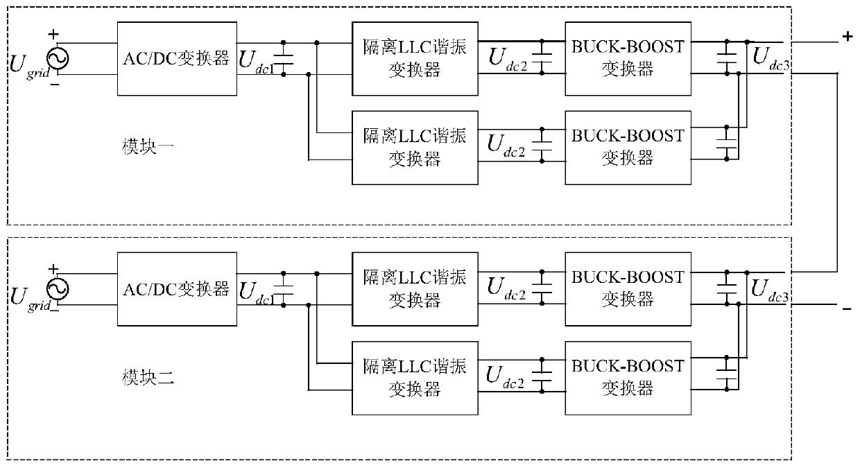
[0063] like figure 1 , which shows a structural block diagram of a system for an aging power supply device according to an embodiment of the present invention.

[0064] When the energy flows in the forward direction, the single-phase AC grid voltage is the input side, and the AC / DC converter circuit rectifies the AC power into DC power, and the primary side DC bus voltage is U. dc1 , U dc1 As the input voltage of the lower-level LLC resonant converter circuit, the output voltage obtained through the transformer life of the resonant converter is the secondary side DC bus voltage U dc2 , U dc2 As the input voltage of the lower-level buck converter circuit, the final desired voltage U is obtained after being boosted by the buck converter circuit dc3 ;

[0065] When the DC side is connected to the power supply, the energy flows in the reverse direction. On the one hand, the DC power supply charges the buck output capacitor of the buck circuit, on the other hand, the remaining en...


PUM


Abstract

The invention discloses a control method for an aging power supply device, and belongs to the field of power electronic system control. The method comprises a control method of a single-phase AC/DC converter circuit, an open-loop control method adopted by an LLC resonant converter, and a control method of a bidirectional BUCK-BOOST converter circuit. Through the control method of the single-phaseAC/DC converter circuit, the DC bus voltage is kept constant, fluctuation of the power grid frequency and distortion of the grid connection current at the non-fundamental frequency are suppressed, andharmonic pollution to the power grid is reduced. Through the adoption of the open-loop control method, the series LLC resonant converter can work in an intermittent mode, the switching loss of the circuit is reduced, and meanwhile, the requirement of boosting between a direct-current bus and the input of the BUCK-BOOST converter circuit is also met. Through the control method of the bidirectionalBUCK-BOOST converter circuit, power sharing by a host and a slave in a constant-current mode is realized, switching tube driving signals of two BUCK-BOOST converters are subjected to phase shifting by 180 degrees to realize interleaved parallel connection, ripples of the current on the output side are reduced, and the quality of the output current is improved.

Description

technical field [0001] The invention belongs to the field of power electronic system control, and relates to a control method for an aging power supply device. Background technique [0002] At present, the country is vigorously implementing energy conservation and emission reduction, promulgating national standards for electric vehicles, encouraging the development of electric vehicles, and green travel. 2015 is the beginning of the rapid development of electric vehicles. There will be a large number of electric vehicles in the market, and the demand for their supporting chargers and charging piles It is very large. In order to meet the market demand, the electric vehicle charger and its energy-saving aging device are specially introduced. [0003] On the one hand, it meets the needs of car manufacturers for the configured chargers, and on the other hand, it solves the problem of aging of other charger manufacturers. Because the power of electric vehicle chargers is large, a...

Claims


Application Information

Patent Timeline
Patent Type & Authority Applications(China)
IPC IPC(8): H02M7/68H02M3/00H02M3/158H02M3/335
CPCH02M3/00H02M3/1582H02M3/33584H02M7/68Y02B70/10
Inventor 粟梅邬思升但汉兵孙尧王辉韩华许国徐菁涛
Owner CENT SOUTH UNIV
Why Eureka
Try Eureka