IGBT module life monitoring method

A life and detection data technology, applied in the field of IGBT modules, can solve the problems of high modeling requirements, high detection circuit response time and precision requirements, and difficult data acquisition, so as to achieve the effect of improving safety and accuracy

Active Publication Date: 2020-01-24
LEADRIVE TECH (SHANGHAI) CO LTD
View PDF14 Cites 5 Cited by
  • Summary
  • Abstract
  • Description
  • Claims
  • Application Information

AI Technical Summary

Problems solved by technology

This method requires power cycle data, loss and junction temperature calculation models, and life models under application conditions, and there are problems such as difficult data acquisition, high modeling requirements, and complex calculations.
[0004] A parameter that characterizes end-of-life for power cycling is the IGBT saturation voltage drop V cesat or diode forward voltage drop V f The change exceeds the allowable value, and some methods will also directly detect V cesat or V f Realize life detection, but this method will have the following problems: For example, when the detection is carried out when there is high voltage, if there is a short circuit in the upper IGBT at this time, and then the lower IGBT is turned on for detection, it may cause the bridge arm to pass through and cause device damage ;Even if the above risks are taken into account, trying to avoid it by shortening the turn-on time will still cause the problem of high requirements for the response time and precision of the detection circuit; in addition, V cesat and V f The value is very small, and the detection is easily disturbed under high pressure
In addition, existing methods simply detect V cesat or V f , the sensed value is compared with a fixed limit, without taking into account the effect of junction temperature on V cesat or V f effects, and differences between modules, can affect the accuracy of lifetime warnings

Method used


Image

  • IGBT module life monitoring method
  • IGBT module life monitoring method
  • IGBT module life monitoring method

Examples


Embodiment Construction

[0019] Below, the structure and working principle of the present invention will be further described in conjunction with the accompanying drawings.

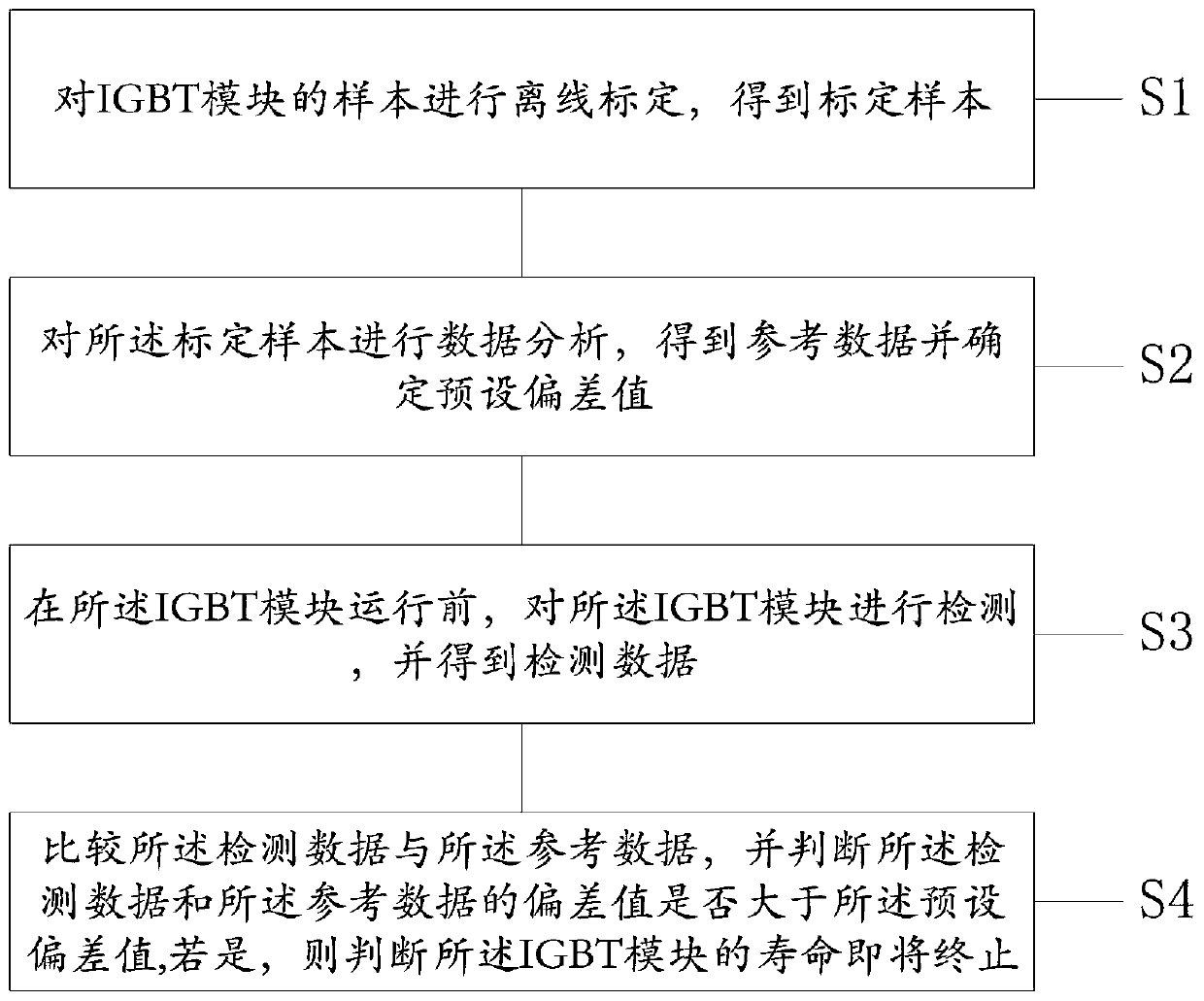
[0020] like figure 1 as shown, figure 1 It is a schematic flow chart of the IGBT module life monitoring method of the present invention; the IGBT module life monitoring method specifically includes the following steps:

[0021] S1 performs offline calibration on samples of IGBT modules to obtain calibration samples; in a preferred embodiment of the present invention, the offline calibration of samples of IGBT modules to obtain calibration samples is specifically: the first saturation of the IGBT module samples Voltage drop V cesat With the first junction temperature T j The change curve of its diode's first forward voltage V f With the first junction temperature T j The change curve of the IGBT module is calibrated off-line, and the calibration curve of the IGBT module sample is obtained as the calibration sample; in order t...


PUM


Abstract

The invention discloses an IGBT module life monitoring method. The IGBT module life monitoring method is characterized by comprising the following steps of: performing off-line calibration on a sampleof the IGBT module to obtain a calibrated sample; performing data analysis on the calibrated sample to obtain reference data and determine a preset deviation value; detecting the IGBT module before the operation of the IGBT module, and obtaining detection data; and comparing the detection data with the reference data, and determining whether a deviation value between the detection data and the reference data is greater than the preset deviation value, and if so, it is judged that the life of the IGBT module is about to end. By means of the IGBT module life monitoring method disclosed by the invention, the monitoring on the life of the IGBT module and a life ending warning can be realized by using a simple and efficient detection method; the IGBT module life monitoring method fully considers the module differences through calibration and statistics; and the IGBT module life monitoring method performs detection under a low voltage, and considers the influence of different junction temperatures, which greatly improves the safety and accuracy of life monitoring.

Description

technical field [0001] The invention relates to the field of IGBT modules, in particular to a method for monitoring the life of an IGBT module. Background technique [0002] At present, in the actual application of the IGBT module, there are frequent power cycles due to the influence of various working conditions. During the working process, the chip is continuously heated and cooled, resulting in changes in the metal coating structure on the chip surface. Repeated micro-changes gradually accumulate, resulting in breakage, displacement or shedding of the bonding wires connected to the chip. Finally, the IGBT module Failure due to end-of-life, resulting in unexpected equipment downtime or greater accidents. Therefore, it is very important to monitor the aging condition of the IGBT module and issue a warning before the end of its life, and it is also a technical problem in this field. [0003] In the prior art, a method for detecting the life of an IGBT is implemented throug...

Claims


Application Information

Patent Timeline
Patent Type & Authority Applications(China)
IPC IPC(8): G01R31/26
CPCG01R31/2642
Inventor 李帆远沈捷
Owner LEADRIVE TECH (SHANGHAI) CO LTD
Why Eureka
Try Eureka