Dual-channel staggered gate slow wave structure

A slow-wave structure, dual-channel technology, applied to the circuit components of transit-time electron tubes, etc., can solve the problem of low coupling impedance value, achieve large power capacity, improve coupling impedance, increase output power and electronic efficiency. Effect

Active Publication Date: 2020-01-24
UNIV OF ELECTRONICS SCI & TECH OF CHINA
View PDF11 Cites 1 Cited by
  • Summary
  • Abstract
  • Description
  • Claims
  • Application Information

AI Technical Summary

Problems solved by technology

[0004] The purpose of the present invention is to provide a double-channel interlaced grating slow-wave structure to solve the problem of low coupling impedance of the existing interleaved double-grid slow-wave structure

Method used


Image

  • Dual-channel staggered gate slow wave structure
  • Dual-channel staggered gate slow wave structure
  • Dual-channel staggered gate slow wave structure

Examples


Embodiment

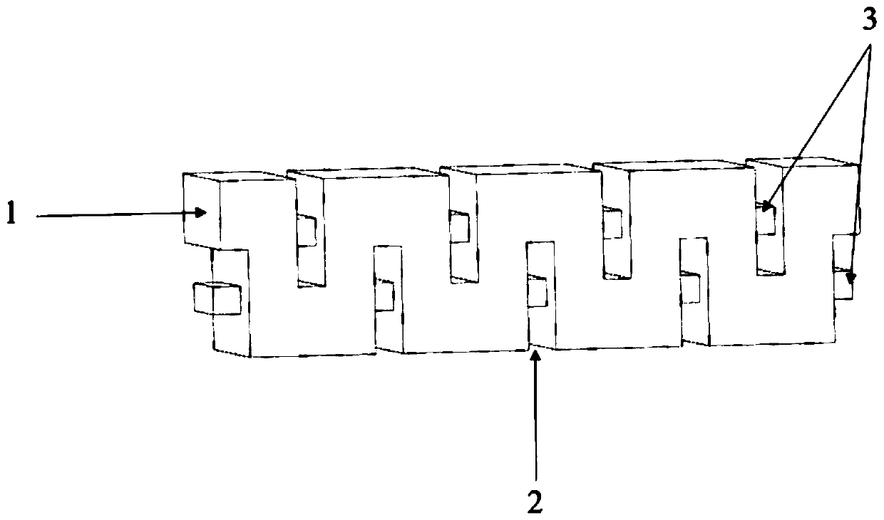
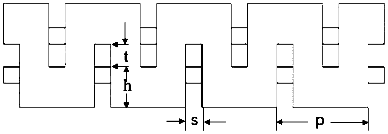
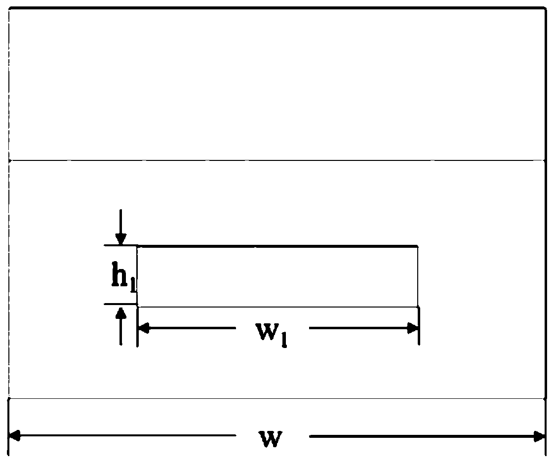
[0029] Such as Figure 1-Figure 3 As shown, the present invention provides a dual-channel staggered grating slow-wave structure, which includes three parts: a rectangular waveguide 1, a rectangular grid 2 and a rectangular channel 3, all of which are made of high-conductivity oxygen-free copper, and the rectangular grid 2 is divided into upper and lower rows. Arranged staggered along the periodic direction, and the height exceeds half of the height of the rectangular waveguide 1, so that the electron injection channel between the upper and lower gates of the staggered double-grid slow-wave structure disappears, the rectangular channel 3 is set in the rectangular grid 2, and the two rows of rectangular channels 3 are respectively set At the top of the two rows of rectangular grids 2 and through the rectangular grids 2 and the rectangular waveguide 1 along the periodic direction, the field distribution of the working mode is concentrated in the region of the beam-wave interaction...


PUM


Abstract

The invention discloses a dual-channel staggered gate slow wave structure comprising a rectangular waveguide which is provided with two rows of rectangular gates. The upper and lower rows of rectangular grates are staggered along the periodic direction. The height of the rectangular gates exceeds half the height of the rectangular waveguide. A rectangular channel for penetrating through the rectangular waveguide is arranged in the rectangular gates. The bottom of the rectangular channel arranged in the upper row of rectangular gates is flush with the top of the lower row of rectangular gates.The top of the rectangular channel arranged in the lower row of rectangular gates is flush with the bottom of the upper row of rectangular gates. The upper row of rectangular channels and the lower row of rectangular channels form double electron beam channels. The natural electron beam channel of the original staggered gates is eliminated by increasing the height of the rectangular gates on the basis of the traditional staggered double gates slow wave structure, and two rows of rectangular channels for penetrating through the rectangular waveguide and the rectangular gates are arranged to form the upper row and the lower row of double electron beam channels so as to effectively improve the coupling impedance and increase the output power and the electron efficiency.

Description

technical field [0001] The invention relates to the technical field of microwave electric vacuum devices, in particular to a double-channel interlaced grid slow-wave structure. Background technique [0002] The terahertz frequency band is a research hotspot in the field of electronic science and technology. It has a wide range of uses in the fields of public security, environmental monitoring, biomedicine, and military fields. The most important. As the most widely used high-power radiation source among many traditional vacuum electronic devices, traveling wave tubes have the characteristics of high power, high efficiency, high gain, broadband and long life, and are widely used in millimeter wave radar, guidance, communication microwave remote sensing It is also praised as the "heart" of weapons and equipment, and its performance directly determines the level of equipment, so it has great research value. However, as the operating frequency increases, in the terahertz frequ...

Claims


Application Information

Patent Timeline
Patent Type & Authority Applications(China)
IPC IPC(8): H01J23/24
CPCH01J23/24
Inventor 丁科森陆志刚朱美玲刘子璇钟宝辉
Owner UNIV OF ELECTRONICS SCI & TECH OF CHINA
Why Eureka
Try Eureka