Flue gas desulfurization and denitration system and method

A desulfurization, denitrification and flue gas technology, applied in the field of flue gas desulfurization and denitrification systems, can solve the problems of high cost, inability to flexibly adjust absorption temperature and absorption flow, etc.

Pending Publication Date: 2020-02-04
GUANGDONG J TECH ENVIRONMENT SCI CO LTD
View PDF3 Cites 1 Cited by
  • Summary
  • Abstract
  • Description
  • Claims
  • Application Information

AI Technical Summary

Problems solved by technology

The desulfurization tower used in this method is composed of a desulfurization sub-tower and a desulfurization main tower, and additional catalysts are required, the cost is high, and the absorption temperature and absorption flow cannot be flexibly adjusted

Method used


Image

  • Flue gas desulfurization and denitration system and method
  • Flue gas desulfurization and denitration system and method
  • Flue gas desulfurization and denitration system and method

Examples


Embodiment 1

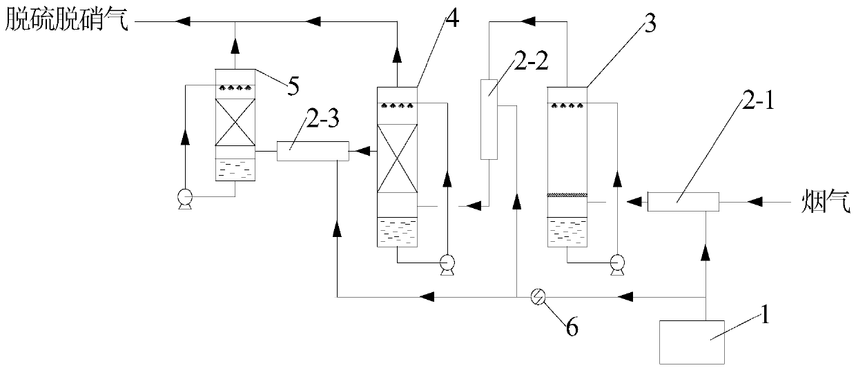
[0057] This embodiment provides a flue gas desulfurization and denitrification system, the structural diagram of the flue gas desulfurization and denitrification system is as follows figure 1 As shown, it includes desulfurization unit, denitrification unit and ozone generation unit.

[0058] The desulfurization unit includes a first mixing device 2-1 and a desulfurization tower 3 connected in sequence, and the flue gas flows into the denitrification tower after passing through the first mixing device 2-1.

[0059] The denitration unit includes a second mixing device 2-2, a first denitration tower 4, a third mixing device 2-3 and a second denitration tower 5, and the gas outlet of the desulfurization tower 3 is connected with the second mixing device 2-2 in sequence. And the first denitration tower 4 is connected; the side outlet of the first denitration tower 4 is connected with the third mixing device 2-3 and the second denitration tower 5 in sequence. The side discharge of ...

Embodiment 2

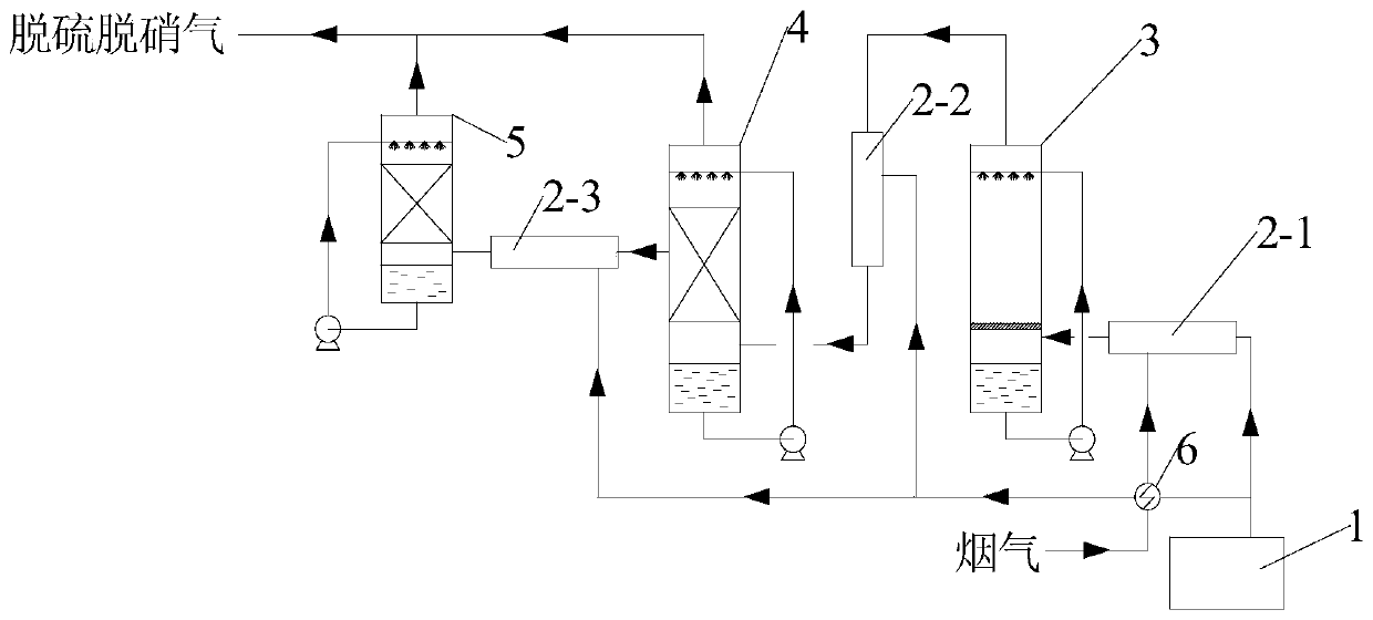
[0065] This embodiment provides a flue gas desulfurization and denitrification system, the structural diagram of the flue gas desulfurization and denitrification system is as follows figure 2 As shown, it includes desulfurization unit, denitrification unit and ozone generation unit.

[0066] The desulfurization unit includes a first mixing device 2-1 and a desulfurization tower 3 connected in sequence, and the flue gas flows into the denitrification tower after passing through the first mixing device 2-1.

[0067] The denitration unit includes a second mixing device 2-2, a first denitration tower 4, a third mixing device 2-3 and a second denitration tower 5, and the gas outlet of the desulfurization tower 3 is connected with the second mixing device 2-2 in sequence. And the first denitration tower 4 is connected; the side outlet of the first denitration tower 4 is connected with the third mixing device 2-3 and the second denitration tower 5 in sequence. The side discharge of...

Embodiment 3

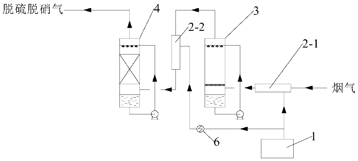
[0073] This embodiment provides a flue gas desulfurization and denitrification system, which is the same as that of Embodiment 1 except that the discharge position of the side line is at the bottom of the packing layer.


PUM

PropertyMeasurementUnit
clearance rateaaaaaaaaaa

Abstract

The invention provides a flue gas desulfurization and denitration system and method. The flue gas desulfurization and denitration system comprises a desulfurization unit, a denitration unit and an ozone generation unit; the denitration unit is divided into two denitration towers, and a material enters the second denitration tower after being discharged from the side line of the first denitration tower, so that the effects of reducing the ozone consumption and improving the denitration temperature and the denitration efficiency are achieved. The flue gas desulfurization and denitration method is simple to operate, the desulfurization and denitration effects are improved under simple operation conditions by reasonably distributing the ratio of ozone to nitric oxide and the liquid-gas ratio and selecting a proper spraying liquid, and the desulfurized and denitrated gas can reach the emission standard after being subjected to aftertreatment.

Description

technical field [0001] The invention belongs to the technical field of waste gas treatment, and relates to a flue gas treatment system and method, in particular to a flue gas desulfurization and denitrification system and method. Background technique [0002] SO emissions from industrial production 2 with NO X It is one of the main sources of air pollution in my country. The current desulfurization and denitrification technologies include wet desulfurization process and selective catalytic reduction process, but the selective catalytic reduction process is not suitable for flue gas and kiln flue gas. The treatment temperature fluctuates greatly and is easy to cause catalyst The basic method for poisoned flue gas and kiln flue gas is wet desulfurization. [0003] NO in flue gas, especially in steel plant flue gas X It mainly comes from the combustion of fuel during the sintering process, and the nitrogen oxides produced during the combustion process are mainly NO and NO 2 ...

Claims


Application Information

Patent Timeline
Patent Type & Authority Applications(China)
IPC IPC(8): B01D53/75B01D53/76B01D53/78B01D53/56B01D53/50
CPCB01D53/502B01D53/56B01D53/75B01D53/76B01D53/78B01D2251/104B01D2251/304B01D2251/306B01D2251/604B01D2258/0283
Inventor 胡静龄杨颖欣钟璐刘勇胡小吐杨森林
Owner GUANGDONG J TECH ENVIRONMENT SCI CO LTD
Why Eureka
Try Eureka