Rapid machining platform and method for grid steel frames

A technology of grid steel frame and processing platform, which is applied in metal processing equipment, earthwork drilling, manufacturing tools, etc. no wait questions

Pending Publication Date: 2020-02-04
CHINA RAILWAY 20 BUREAU GRP
View PDF0 Cites 3 Cited by
  • Summary
  • Abstract
  • Description
  • Claims
  • Application Information

AI Technical Summary

Problems solved by technology

[0003] At present, when constructing tunnels, there are mainly the following problems in the processing of grid arches (that is, grid steel frames): First, the number of grid steel frames used for the initial support of tunnels is huge, and the processing volume of grid steel frames is large: Each grille steel frame is spliced ​​by multiple steel frame segments, and the multiple segments of the grille steel frame need to be processed separately, which further increases the processing amount of the grille arch frame, and the processing process costs Time-consuming, large processing costs are required, and the input of manpower and material resources is very large, especially for the construction of long tunnels. The processing volume of the grid arch frame is even greater; There are many specifications: grid steel frames of different specifications are required in tunnel sections with different surrounding rock levels in the same tunnel, and the structures and sizes of grid steel frames supported on tunnel sections with different structures and different settlements are different. As a result, there are many specifications of the grid steel frame, which further increases the difficulty of processing the grid steel frame; third, since the tunnel construction is carried out based on advanced geological forecast and monitoring measurement information, different geological conditions need to dynamically adjust the corresponding tunnel The reserved deformation of the section will cause corresponding changes in the specifications and dimensions of the grid steel frame processing, and the number of grid steel frames that need to be processed each time is not large, and mass production cannot be realized because the tunnel is located in...

Method used


Image

  • Rapid machining platform and method for grid steel frames
  • Rapid machining platform and method for grid steel frames
  • Rapid machining platform and method for grid steel frames

Examples


Embodiment Construction

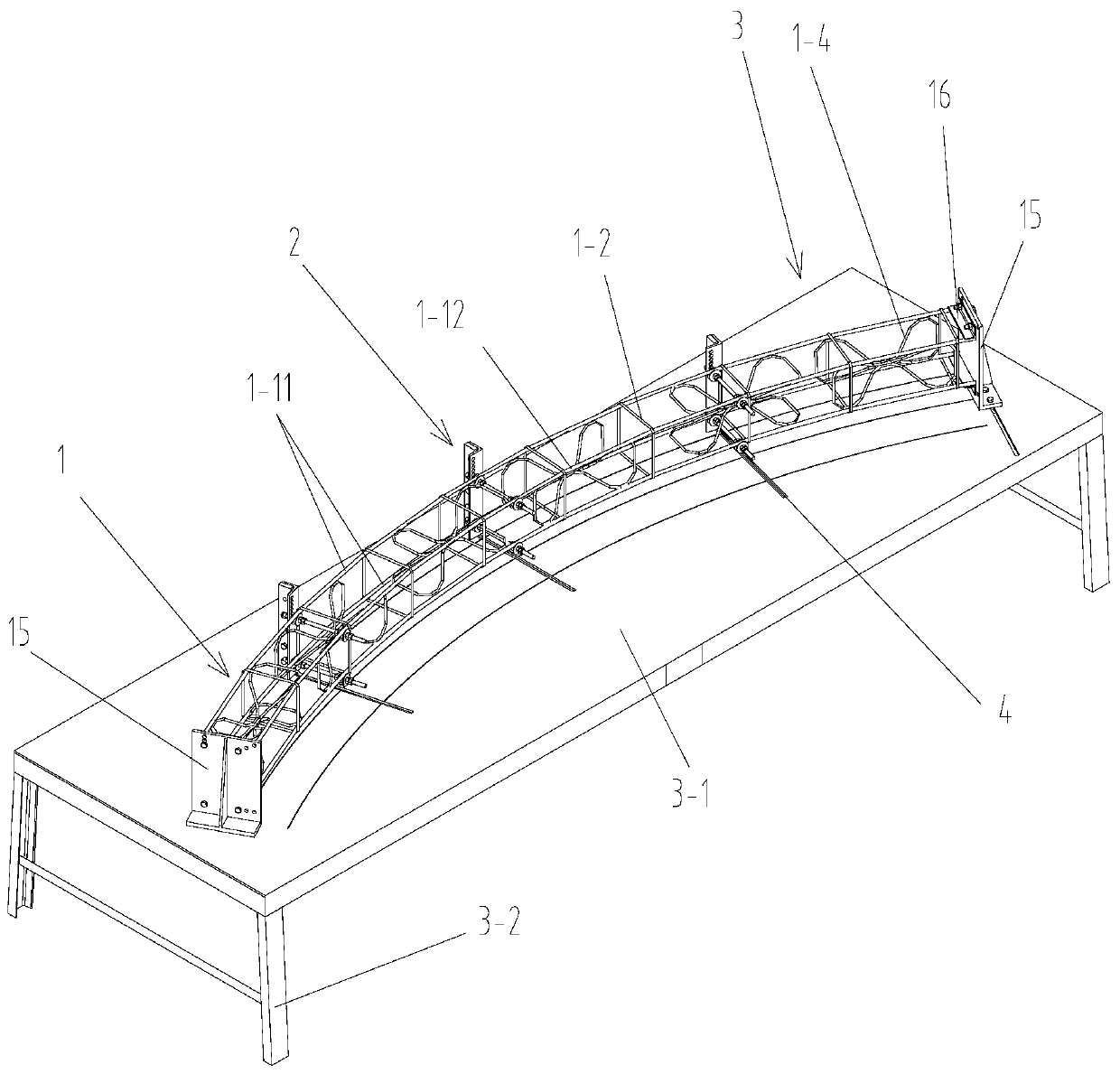
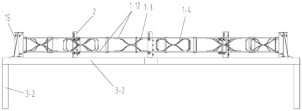
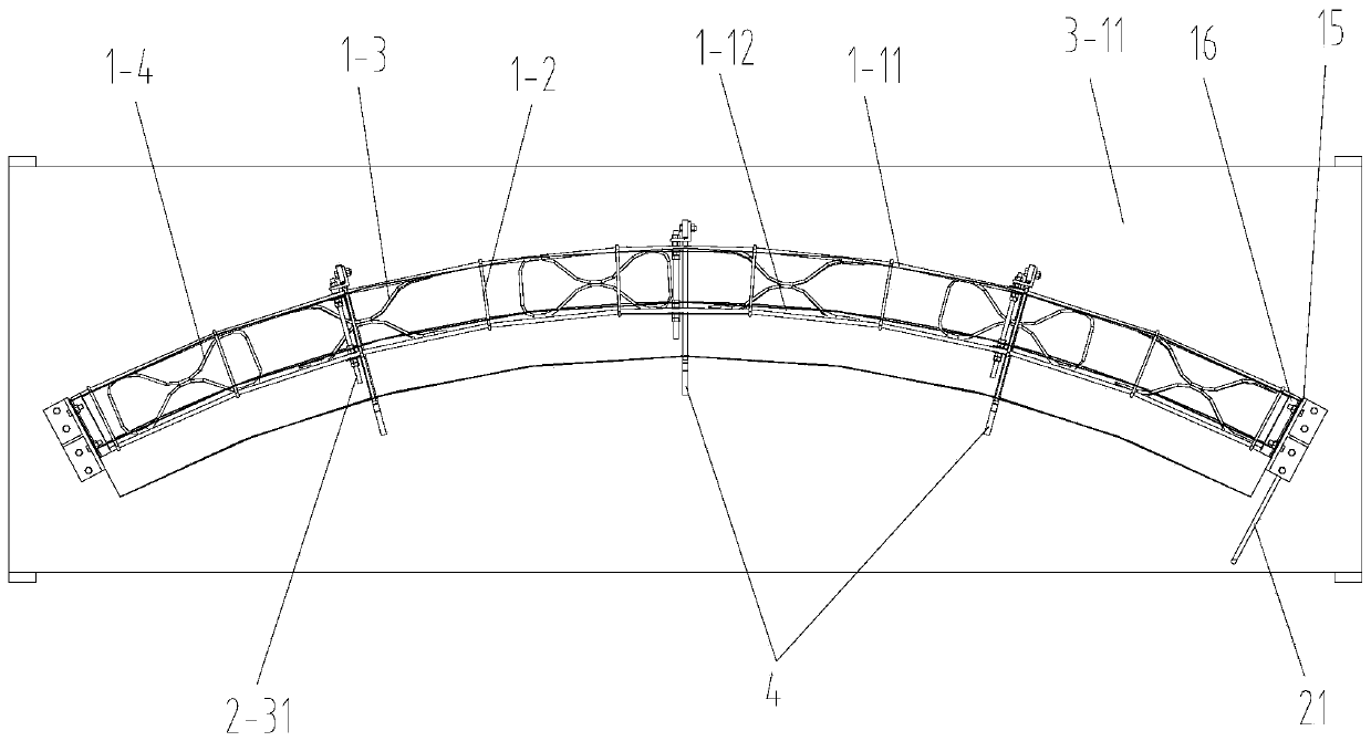
[0088] like figure 1 , figure 2 and image 3 A grid steel frame rapid processing platform shown includes a horizontal support platform 3 and a plurality of main reinforcement positioning molds 2 for synchronous positioning of the steel frame segment 1 to be processed, and a plurality of main reinforcement positioning molds 2 are arranged along the circumferential direction and They are all installed on the horizontal support platform 3, the structure and size of the plurality of main rib positioning molds 2 are the same, and the steel frame segment 1 to be processed is arranged horizontally and is located above the horizontal support platform 3;

[0089] combine Figure 25 , the steel frame segment 1 to be processed is a steel frame segment in the grid steel frame for the initial support of the tunnel hole 17, and the grid steel frame includes a steel frame for supporting the arch wall of the tunnel hole 17 Arch wall support 18, the shape of the arch wall support 18 is the...


PUM


Abstract

The invention discloses a rapid machining platform and method for grid steel frames. The machining platform comprises a horizontal support platform and a plurality of main reinforcement positioning moulds, wherein the plurality of main reinforcement positioning moulds are laid in the circumferential direction and all mounted on the horizontal support platform; the plurality of main reinforcement positioning moulds form a main reinforcement positioning device for positioning four main reinforcements in a to-be-machined steel frame segment; and each main reinforcement positioning mould comprisesa sliding seat, a connection seat and a main reinforcement positioning mechanism. The method comprises the steps of 1, adjusting the main reinforcement positioning mechanisms; 2, adjusting the positions of the main reinforcement positioning moulds; 3, mounting the main reinforcements; 4, fixing dowels of the main reinforcements; and 5, fixing rectangular stirrups. The machining platform and method are reasonable in design, simple and convenient in strengthening and good in using effect; and the plurality of movable main reinforcement positioning moulds are adopted to position the steel framesegments and the main reinforcement positioning mechanism on each main reinforcement positioning mould can be adjusted according to the widths and thicknesses of the machined steel frame segments, sothat the machining demands of the steel frame segments with different specifications can be satisfied.

Description

technical field [0001] The invention belongs to the technical field of tunnel grid steel frame processing, and in particular relates to a grid steel frame rapid processing platform and a processing method. Background technique [0002] Tunnel arch frame is used to support caves or bunkers during the construction of tunnel projects (such as highway tunnel projects, railway tunnel projects, military concealed projects, mines, coal mines, iron mines and other roadways, water diversion tunnels for hydropower stations, etc.) The steel brackets are generally made of section steel or steel bars according to a certain radian and length, and are made into individual units, and then installed at the construction site, followed by anchor rod installation, longitudinal connection steel bar welding and steel mesh welding, and finally Shotcrete construction is carried out, and the initial support in the tunnel construction is completed after the anchor shotcrete is completed. Tunnel arch...

Claims


Application Information

Patent Timeline
IPC IPC(8): B23K31/02B23K37/04B23P15/00B21F1/00E21D11/18
CPCB21F1/00B23K31/02B23K37/04B23P15/00E21D11/18
Inventor 谢江胜崔润兵仲维玲曹运祥刘之涛马传明张会安井发岳王建军杨朝李强张良
Owner CHINA RAILWAY 20 BUREAU GRP
Why Eureka
Try Eureka