
Supersonic engine test stand and test method thereof

An engine and supersonic technology, which is applied in engine testing, machine/structural component testing, force/torque/power measuring instruments, etc., can solve problems such as cost increase, large footprint, and noise reduction ability, and achieve structural Simple, simple method, high simulation accuracy

Pending Publication Date: 2020-02-04
BEIJING AEROSPACE SANFA HIGH TECH
View PDF4 Cites 3 Cited by
  • Summary
  • Abstract
  • Description
  • Claims
  • Application Information

AI Technical Summary

Problems solved by technology

[0006] For the noise reduction method for the noise generated by the test bench, there is no very mature and effective technical means in the prior art. The applicant first applied for CN203910262U, and proposed a muffler, which has a certain effect on the noise reduction and noise reduction of the test bench. , but the staggered arrangement of the muffler's thick-plate components and thin-plate components requires a large footprint. Sheet components and sheet components (each layer of sound absorbing sheet components requires at least 2 thick sheet components of the muffler and 2 thin sheet components of the muffler plus half a thick sheet assembly of the muffler and a half sheet assembly of the muffler), resulting in a significant increase in cost; another On the one hand, when the floor area of ​​the engine test bench that allows the installation of sound-absorbing equipment is small and does not allow the staggered arrangement of thick-sheet components and thin-sheet components of the muffler described in this patent application, removing any piece of sound-absorbing sheet will result in a loss of sound-absorbing capability. Decline

Method used


Image

  • Supersonic engine test stand and test method thereof
  • Supersonic engine test stand and test method thereof
  • Supersonic engine test stand and test method thereof

Examples


Embodiment Construction

[0049] In describing the present invention, it should be understood that the terms "center", "longitudinal", "transverse", "length", "width", "thickness", "upper", "lower", "front", " Back", "Left", "Right", "Vertical", "Horizontal", "Top", "Bottom", "Inner", "Outer", "Clockwise", "Counterclockwise", "Axial", The orientation or positional relationship indicated by "radial", "circumferential", etc. is based on the orientation or positional relationship shown in the drawings, and is only for the convenience of describing the present invention and simplifying the description, rather than indicating or implying the referred device or element Must be in a particular orientation, be constructed in a particular orientation, and operate in a particular orientation, and therefore should not be construed as limiting the invention. In addition, the features defined as "first" and "second" may explicitly or implicitly include one or more of these features. In the description of the prese...


PUM


Abstract

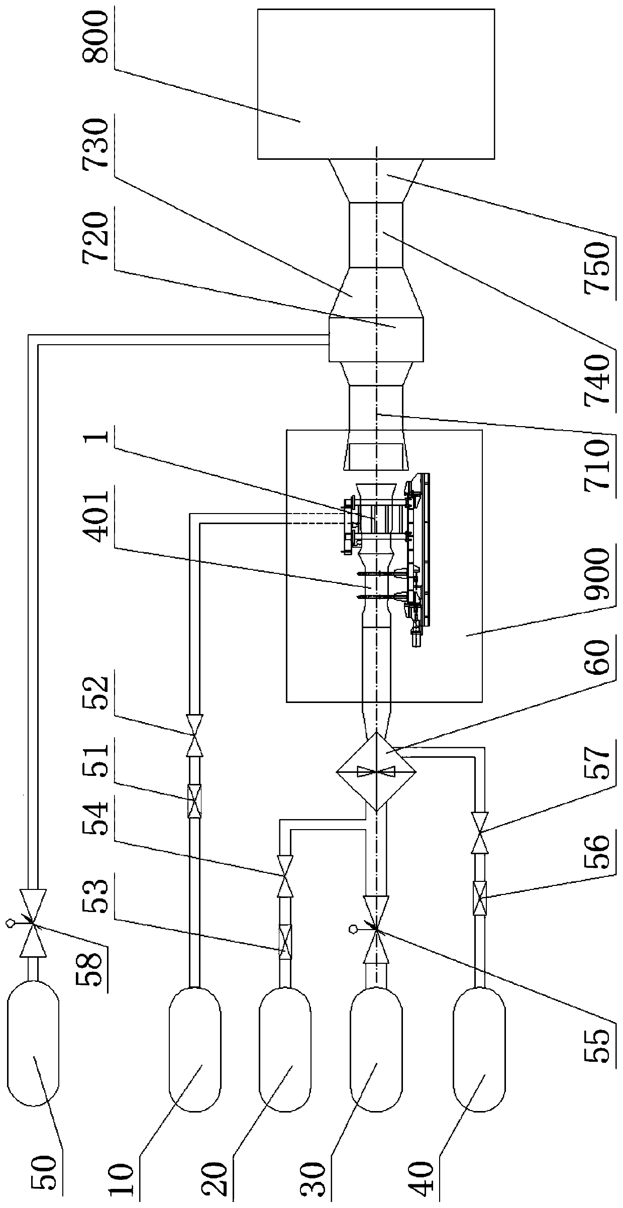
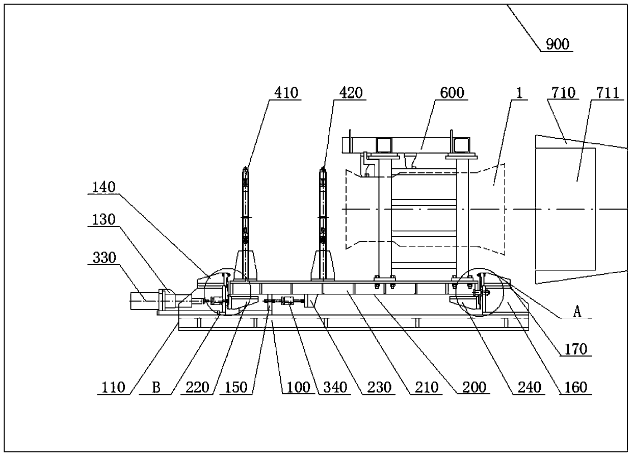
The invention provides a supersonic engine test stand. A high-altitude simulation cabin is of a sealed shell structure. An engine thrust measurement platform is fixedly installed in the high-altitudesimulation cabin. A tested engine is installed on the engine thrust measurement platform. An air inlet system is in communication with the tested engine or an exhaust system. One end of the exhaust system penetrates through the shell surface of the high-altitude simulation cabin and is fixedly installed in the high-altitude simulation cabin, and the other end of the exhaust system is in fixed communication with an exhaust gas treatment system. The supersonic engine test stand realizes the simulation of a supersonic air inlet state of a supersonic engine during ground tests of the supersonic engine and the engine; meanwhile, the engine thrust measurement platform realizes the measurement of engine thrust, and the structure is simple; in addition, the treatment of exhaust gas from the enginetest stand is realized, so that the gas discharged from an air outlet of an alkaline spray tower meets the national pollutant emission standard; and a noise reduction tower is arranged, the exhaust of the exhaust system is subjected to noise reduction, and noise pollution is avoided.

Description

technical field [0001] The invention relates to the technical field of engine testing, in particular to a supersonic engine test bench and a testing method thereof. Background technique [0002] Engine testing and testing technology is an important part of solid propulsion technology. Before the flight test of an aeroengine, a high-altitude simulation test needs to be done on the ground. During the engine test, a set of intake parameters are required, including the total intake pressure and the intake air flow rate. , intake air oxygen content, total intake air temperature, and engine fuel supply are called intake state points. After reaching the set value and stabilizing at the same time, record its performance and parameters or evaluate its performance. With the maturity of the engine, the application of the supersonic engine is becoming more and more extensive. On this basis, the engine intake system needs to simulate the supersonic speed of the supersonic engine when it ...

Claims


Application Information

Patent Timeline
IPC IPC(8): G01M15/00G01M15/02G01L5/00
CPCG01L5/0038G01M15/00G01M15/02
Inventor 许海涛王文彬周培好
Owner BEIJING AEROSPACE SANFA HIGH TECH
Learn More