A kind of compound fertilizer and its production device and production method
A technology of compound fertilizer and production device, which is applied in the direction of fertilization device, urea compound fertilizer, inorganic fertilizer, etc., to achieve the effect of good mixing and stirring effect and the effect of improving quality
- Summary
- Abstract
- Description
- Claims
- Application Information
AI Technical Summary
Problems solved by technology
Method used
Image
Examples
Embodiment 1
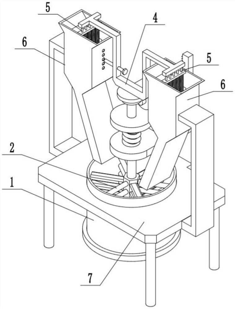
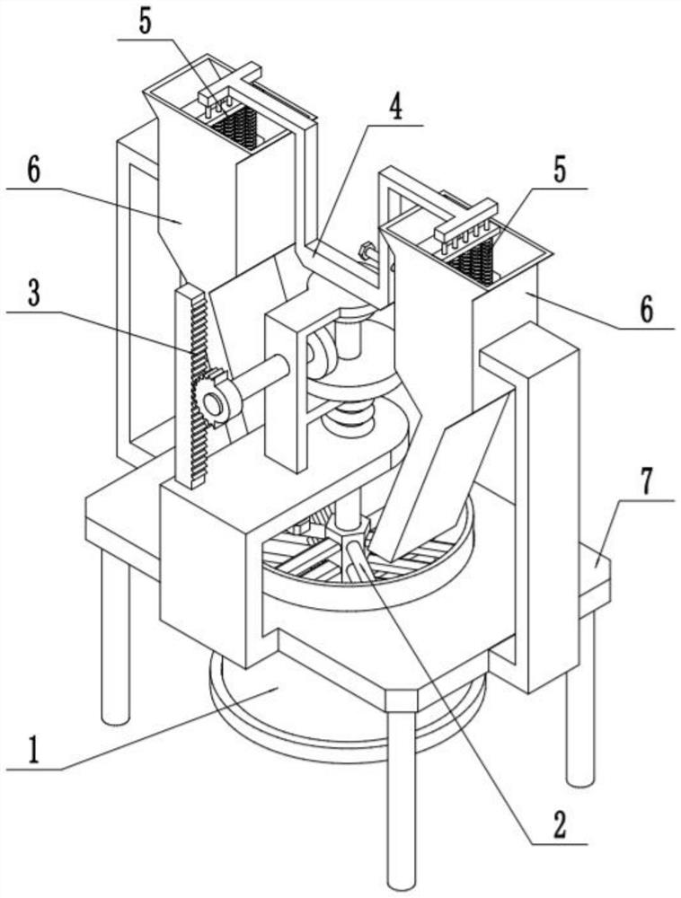
[0036] like Figure 1-11 As shown, a compound fertilizer production device includes a mixing drum 1 with an opening at the top, an agitator 2, a rack 3, a linkage frame 4, a feeding controller 5, a raw material box 6 and a frame 7, and the mixing drum 1 is connected to On the frame 7; one end of the agitator 2 is rotatably fitted in the mixing drum 1, and the other end of the agitator 2 is connected to the frame 7; the agitator 2 is connected with the rack 3, and the rack 3 is fixed On the agitator 2; the agitator 2 is connected to the linkage frame 4 by transmission, and the two ends of the linkage frame 4 are connected with two feed controllers 5; the two feed controllers 5 are respectively connected in a raw material box 6; Each of the raw material boxes 6 is fixed on the frame 7 , and the discharge ports of the two raw material boxes 6 are located just above the top opening of the mixing drum 1 . In the compound fertilizer production device of the present invention, when ...
Embodiment 2
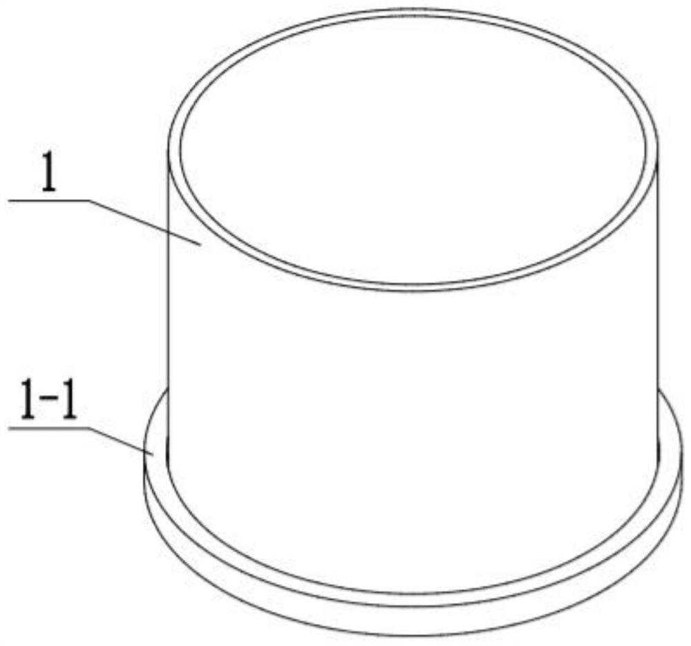
[0038] like Figure 1-11 As shown, the lower part of the mixing cylinder 1 is open, and the lower part of the mixing cylinder 1 is connected to the cylinder cover 1-1 through screw fitting. The cylinder cover 1-1 is easy to disassemble, so as to discharge the stirred raw materials.
Embodiment 3
[0040] like Figure 1-11As shown, the agitator 2 includes a stirring motor 2-1, a stirring shaft 2-2, a stirring part 2-3, a transmission bevel gear 2-4, a driven bevel gear 2-5, a linkage shaft 2-6, an irregular gear 2-7. Tension spring 2-8, upper bracket 2-9 and lower bracket 2-10; the stirring motor 2-1 is fixed on the upper bracket 2-9; the upper bracket 2-9 is slidably fitted on the lower bracket 2-10; the lower bracket 2-10 is fixed on the frame 7; the output shaft of the stirring motor 2-1 is connected with the stirring shaft 2-2 through a coupling; the stirring shaft 2-2 is rotated and matched Connected to the upper bracket 2-9, the stirring shaft 2-2 is slidably fitted on the lower bracket 2-10; the stirring shaft 2-2 is fixed with a transmission bevel gear 2-4; the transmission bevel gear 2-4 meshes and drives The driven bevel gear 2-5 is connected; the driven bevel gear 2-5 and the irregular gear 2-7 are respectively fixed on both ends of the linkage shaft 2-6; the...
PUM
 Abstract
Description
Claims
Application Information
 - R&D
- Intellectual Property
- Life Sciences
- Materials
- Tech Scout
- Unparalleled Data Quality
- Higher Quality Content
- 60% Fewer Hallucinations
Browse by: Latest US Patents, China's latest patents, Technical Efficacy Thesaurus, Application Domain, Technology Topic, Popular Technical Reports.
© 2025 PatSnap. All rights reserved.Legal|Privacy policy|Modern Slavery Act Transparency Statement|Sitemap|About US| Contact US: help@patsnap.com


