Heat recovery heat supply system of distributed data center

A technology of distributed data and heating system, applied in the intersection of HVAC and information network, can solve the problems of large area of ​​centralized data center, high construction and operation and maintenance costs, and difficulty in heat dissipation, so as to control the operation cost, Easy maintenance and replacement, high heat dissipation effect

Active Publication Date: 2020-02-07
NANJING UNIV OF AERONAUTICS & ASTRONAUTICS
View PDF11 Cites 3 Cited by
  • Summary
  • Abstract
  • Description
  • Claims
  • Application Information

AI Technical Summary

Problems solved by technology

[0004] The invention provides a distributed data center heat recovery and heating system, which can use the heat of the server for home heating, and disperse the heat of the server to the surrounding environment when no heating is needed, so as to solve the problem of large area occupied by the centralized data center and construction problems. And the shortcomings of high operation and maintenance costs and difficult heat dissipation, and at the same time make full use of the heat dissipation of the device server to provide heat for the home

Method used


Image

  • Heat recovery heat supply system of distributed data center
  • Heat recovery heat supply system of distributed data center
  • Heat recovery heat supply system of distributed data center

Examples


Embodiment 1

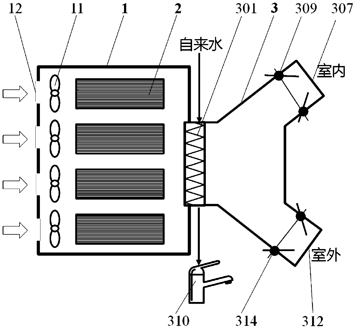
[0039] The distributed data center heat recovery heating system provided in this embodiment, such as figure 2 As shown, it includes: a cabinet 1, a server 2, and a heat recovery and heating module 3. The server 2 is discretely installed in the cabinet 1 , and the cabinet 1 is connected to the heat recovery and heating module 3 , and a cooling fan 11 and an air vent 12 are also arranged in the cabinet 1 .

[0040] The heat recovery heating module 3 includes a heat exchanger 301 , an indoor air outlet pipe 307 , an indoor air outlet pipe damper 309 , an outdoor air outlet pipe 312 , and an outdoor air outlet pipe damper 314 .

[0041] One side of the heat exchanger 301 is embedded in the cabinet 1, and the other side is connected to the indoor air outlet pipe 307 and the outdoor air outlet pipe 312 respectively through a structure similar to a three-way pipe. The indoor air outlet pipe 307 is installed indoors and connected to the indoor air outlet pipe. The air outlet pipe damp...

Embodiment 2

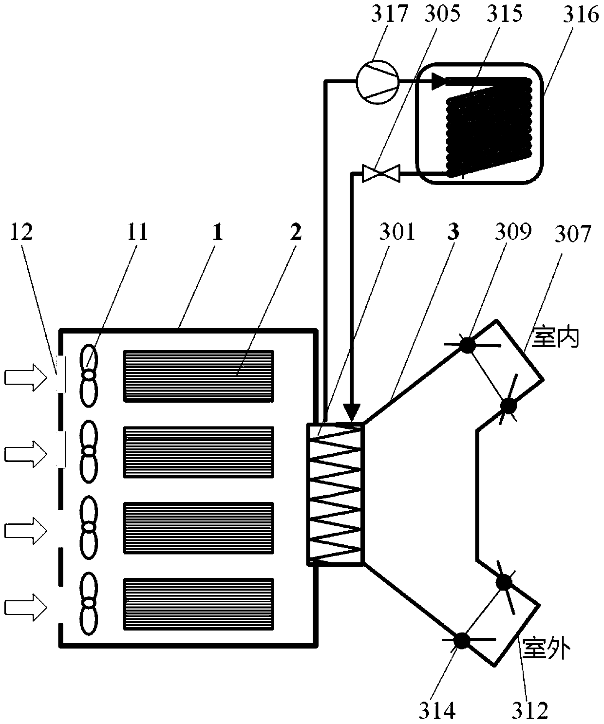
[0045] Embodiment 2 On the basis of Embodiment 1, a water-cooled coil condenser 315 and a heat storage tank 316 are added. The input end of the water-cooled coil condenser 315 is connected to the refrigerant outlet of the heat exchanger 301 through a compressor 317 , and the output end of the water-cooled coil condenser 315 is connected to the refrigerant inlet and outlet of the heat exchanger 301 through a throttling device 305 . The water-cooled coil condenser 315 is arranged inside the heat storage tank 316, such as image 3 shown.

[0046] When the compressor 317 and the throttling device 305 are turned on, and the air valve 309 of the indoor air outlet pipe and the indoor air outlet pipe 307 are closed, based on the principle of forced convection, the heat recovery heating module 3 operates in the heat pump circulation mode to obtain a higher temperature The domestic hot water is stored in the hot water storage tank 316 .

[0047] The working method of this embodiment i...

Embodiment 3

[0053] This example Figure 5 As shown, it includes a cabinet 1, a server 2, and a heat recovery and heating module 3. Wherein, the heat recovery heating module 3 includes an evaporator 302, a compressor 317, a heat dissipation branch valve 308, an air-cooled condenser 311, a heat storage branch valve 313, a water-cooled coil condenser 315, a heat storage tank 316, a flow device 305 . The heat dissipation branch valve 308 is connected with the air-cooled condenser 311 to form a heat dissipation branch; the heat storage branch valve 313, the water-cooled coil condenser 315, and the hot water storage tank 316 form a heat storage branch, and the heat storage branch valve 313 is connected to the water-cooled The coil condenser 315 and the cold coil condenser 315 are arranged inside the heat storage tank 316 .

[0054] The evaporator 302 is connected in parallel with the heat dissipation branch and the heat storage branch respectively, and the input ends of the evaporator 302 and...


PUM


Abstract

The invention discloses a heat recovery heat supply system of a distributed data center, and relates to the field of heating ventilation air conditioners and information network crossover. The systemcomprises a cabinet, servers and a heat recovery heat supply module. The servers are located in the cabinet, and are placed in a user home, and data calculation and storage capacity is provided for local and remote users; the heat recovery heat supply module recycles waste heat of the servers for supplying heat to local users; servers originally placed in a concentrated manner are placed in the user home and the local communities in a dispersed, the heat dissipation amount of the servers is used for supplying heat to the user home, the waste heat use rate of the data center is improved, when heat supply is not needed, redundant heat is emitted to the surrounding, heat dissipation is disperse, efficiency is higher, a local heat stack effect is effectively weakened, and stable running of theservers is ensured; and the defects of large occupied area, high building and maintaining cost and difficult heat dissipation of a centralized data center can be overcome, and dissipated heat of theservers of the center can be used for supplying heat to the home.

Description

technical field [0001] The invention relates to the intersecting field of HVAC and information network, in particular to a distributed data center heat recovery heating system. Background technique [0002] With the exponential growth of the amount of processed data, the data center (IDC) as a data storage / exchange hub is developing rapidly. According to statistics, at present, the number of various data centers in my country has exceeded 500,000, and the number of cabinets has exceeded 6 million. The number and area of ​​data centers have leapt to the second place in the world. The data center is developing very fast and the market potential is huge. However, traditional centralized data centers have the following problems: 1) In traditional data centers, all electronic equipment is usually placed centrally, which makes the heat dissipation of the equipment too large and concentrated (the heat dissipation per unit area reaches 1000W / m2), making it difficult to dissipate he...

Claims


Application Information

Patent Timeline
IPC IPC(8): F24D15/02H05K7/20
CPCF24D15/02H05K7/20709H05K7/20818H05K7/20736
Inventor 张朋磊陈航刘书庭赖柄竹王宁悦刘梓煊
Owner NANJING UNIV OF AERONAUTICS & ASTRONAUTICS
Why Eureka
Try Eureka