
Photocatalytic evaluation characterization device and method for carbon dioxide reduction

A carbon dioxide and carbon monoxide technology, which is used in measurement devices, chemical analysis by catalysis, instruments, etc., can solve the problems of cumbersome process flow, increase production cost, short service life, etc., and achieve simple process operation, simple installation and layout, The effect of low input cost

Pending Publication Date: 2020-02-07
XIAN UNIV OF SCI & TECH
View PDF0 Cites 6 Cited by
  • Summary
  • Abstract
  • Description
  • Claims
  • Application Information

AI Technical Summary

Problems solved by technology

[0004] First, the structure of the photocatalytic device is complex, which makes the device cumbersome in the process and increases the production cost; at the same time, the photocatalytic reaction device of some devices is made of integral quartz material, which is fragile in the actual photocatalytic experimental operation and has a long service life. shorter;
[0005] Second, the photocatalytic device is a closed system. In the later stage of the reaction, because the concentration of other gases such as CO2 no longer increases, the reaction product gas cannot be moved out of the photocatalytic device, and the balance of the chemical reaction occurs. The amount of the reaction product gas no longer increases, thus affecting The activity of the catalyst and the efficiency of the product in the reaction
[0006] Third, the light source for photocatalysis in the photocatalytic device is exposed. The exposed light source will bring certain light pollution hazards to the operator while carrying out the photocatalytic reaction. Long-term exposure to ultraviolet lamps and other light sources will cause damage to the eyes and skin of the experimenter. damage

Method used


Image

  • Photocatalytic evaluation characterization device and method for carbon dioxide reduction
  • Photocatalytic evaluation characterization device and method for carbon dioxide reduction
  • Photocatalytic evaluation characterization device and method for carbon dioxide reduction

Examples


Embodiment Construction

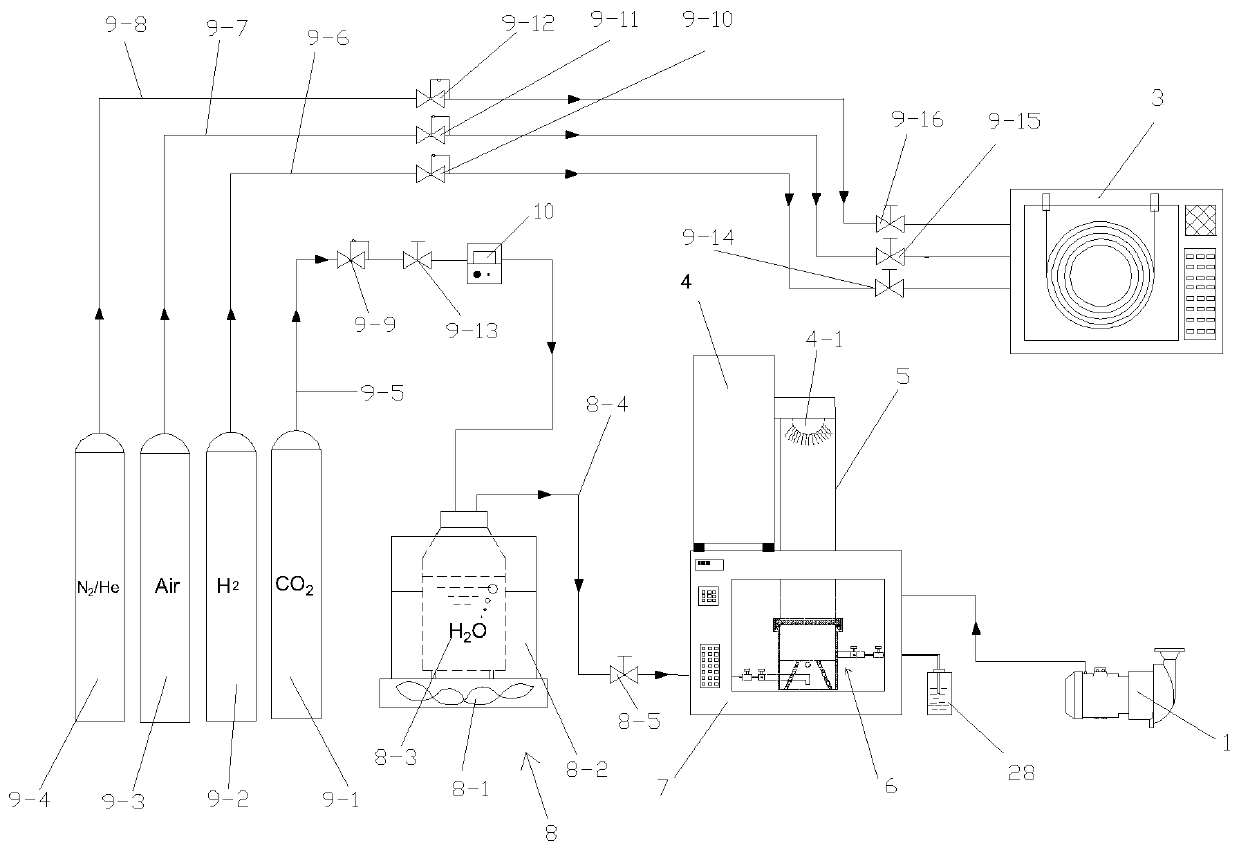
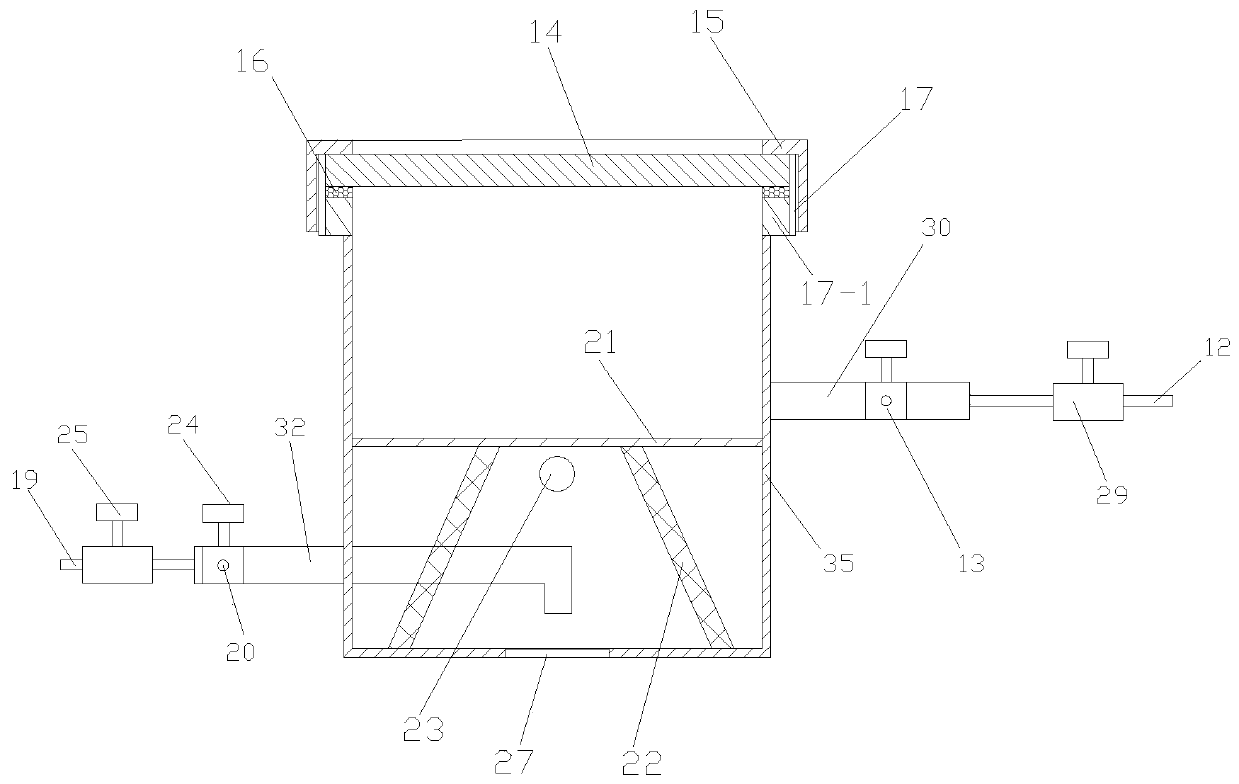
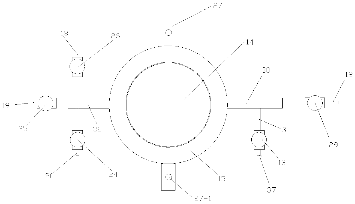
[0092] like Figure 1 to Figure 3 The shown photocatalytic evaluation and characterization device for carbon dioxide reduction includes a photocatalytic mechanism, a gas path mechanism, a water vapor generating mechanism 8 and a gas chromatograph 3, and the photocatalytic mechanism includes a blast drying box 7, which is arranged in a blast drying oven. The light source parts on the top of the box 7 and the catalytic reactor 6 arranged in the blast drying box 7, and the vacuum pump 1 connected with the catalytic reactor 6, the catalytic reactor 6 includes a reaction tank, is arranged in the reaction tank The four-corner support frame for placing photocatalyst and the inlet pipeline parts and outlet pipeline parts arranged on the reaction tank, the four-corner support frame includes activated carbon carrier net 21 for placing photocatalyst and four symmetrically arranged on activated carbon carrier The support leg 22 at the bottom of the net 21, the bottom of the support leg 22...


PUM

PropertyMeasurementUnit
Granularityaaaaaaaaaa

Abstract

The invention discloses a photocatalytic evaluation characterization device and method for carbon dioxide reduction. The device comprises a photocatalysis mechanism, a gas path mechanism, a water vapor generation mechanism and a gas chromatograph, the photocatalysis mechanism comprises a blast drying box, a light source part, a catalytic reactor and a vacuum pump, the catalytic reactor comprises areaction tank, a four-corner supporting frame, an inlet pipeline part and an outlet pipeline part, and the four-corner supporting frame comprises an activated carbon carrying net and supporting legs.The method comprises the following steps of: 1, preparing a photocatalyst; 2, connecting and debugging the device; 3, filling the photocatalyst; 4, performing preparation before reaction; 5, carryingout photocatalytic reduction reaction on carbon dioxide; 6, detecting the concentration of methane gas and the concentration of carbon monoxide gas; and 7, obtaining the optimal photocatalyst for preparing methane and the optimal photocatalyst for preparing carbon monoxide. The photocatalytic evaluation characterization device and method for carbon dioxide reduction are reasonable in design, andimprove the accuracy of photocatalytic evaluation characterization of carbon dioxide reduction.

Description

technical field [0001] The invention belongs to the technical field of carbon dioxide reduction, and in particular relates to a photocatalytic evaluation and characterization device and method for carbon dioxide reduction. Background technique [0002] As the global economy develops and consumes dwindling fossil fuel reserves, the combustion of fossil fuels is accompanied by a large amount of anthropogenic CO 2 emissions, which far exceed nature's CO 2 Recycling capacity, which leads to the increasingly serious problem of global warming, makes this environmental crisis a hot issue of concern to all countries in the world, and the reduction of CO 2 Excessive emissions of greenhouse gases represented by GHG are very important for solving the problem of global warming. Traditional research has largely focused on the CO 2 direct storage after capture, or CO 2 Captured and reused, mostly for the production of chemicals and other industrial products, while captured CO 2 The m...

Claims


Application Information

Patent Timeline
IPC IPC(8): G01N31/10G01N30/02
CPCG01N31/10G01N30/02
Inventor 周安宁李瑞琪张亚刚李高峰赵小玲凌洁段飞扬
Owner XIAN UNIV OF SCI & TECH
Learn More