
Bayesian radar correlated imaging method based on disturbance matrix estimation

A correlative imaging and Bayesian technology, applied in the field of target tracking, can solve the problems of model mismatch, affecting the reconstruction performance of radar target scattering coefficient, low resolution, etc., and achieve the effect of reducing mismatch

Active Publication Date: 2020-02-07
XIDIAN UNIV
View PDF5 Cites 1 Cited by
  • Summary
  • Abstract
  • Description
  • Claims
  • Application Information

AI Technical Summary

Problems solved by technology

[0004] However, in reality, there are many factors that cause errors in the radar model. The combined effect of these factors will cause errors in the reference matrix, resulting in model mismatch
Reconstruction performance of radar target scattering coefficients due to model mismatch
For the matrix perturbation problem, the existing methods construct and solve the regularized total least squares optimization problem under the sparse constraint, and have achieved certain results for the point target scene, but there will be a problem of low resolution for the complex scene; for the model The radar theoretical reference matrix under mismatch is disturbed by a Gaussian white noise that satisfies zero mean value. An improved underdetermined system solution method for radar correlation imaging under model mismatch is proposed. However, this algorithm depends on the initialization value setting, under imaging conditions such as large model error and low signal-to-noise ratio, the radar super-resolution imaging performance is poor

Method used


Image

  • Bayesian radar correlated imaging method based on disturbance matrix estimation
  • Bayesian radar correlated imaging method based on disturbance matrix estimation
  • Bayesian radar correlated imaging method based on disturbance matrix estimation

Examples


Embodiment 1

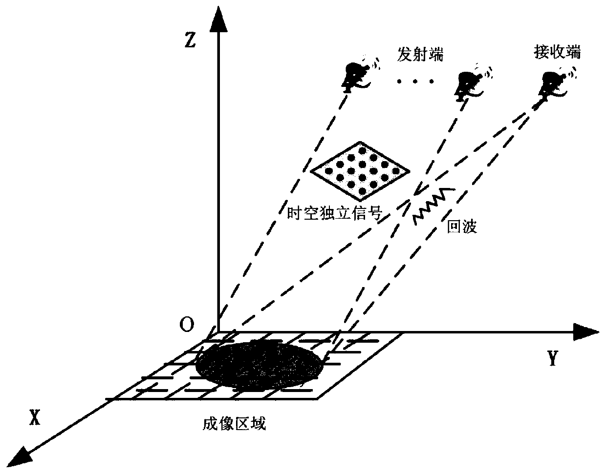
[0042] As a new radar imaging technology, radar correlation imaging has shown great advantages in improving imaging resolution. The main process of classic optical correlation imaging is: an incoherent thermal light source emits two highly correlated optical signals, which are called detection signals and reference signals, and the transmission coefficient of the target can be reconstructed by correlating the reference signal with the received signal . Based on the study of classical optical imaging, it can be concluded that radar correlation imaging mainly obtains the inversion image of the radar detection area by correlating the radiation field and the target scattering field. When using radar correlation imaging, the radar array can be regarded as It is the signal source of radar correlation imaging. The signal emitted by each array element is the signal radiated by the entire signal source at different spatial positions, and the superposition of the emitted signals of all ...


PUM


Abstract

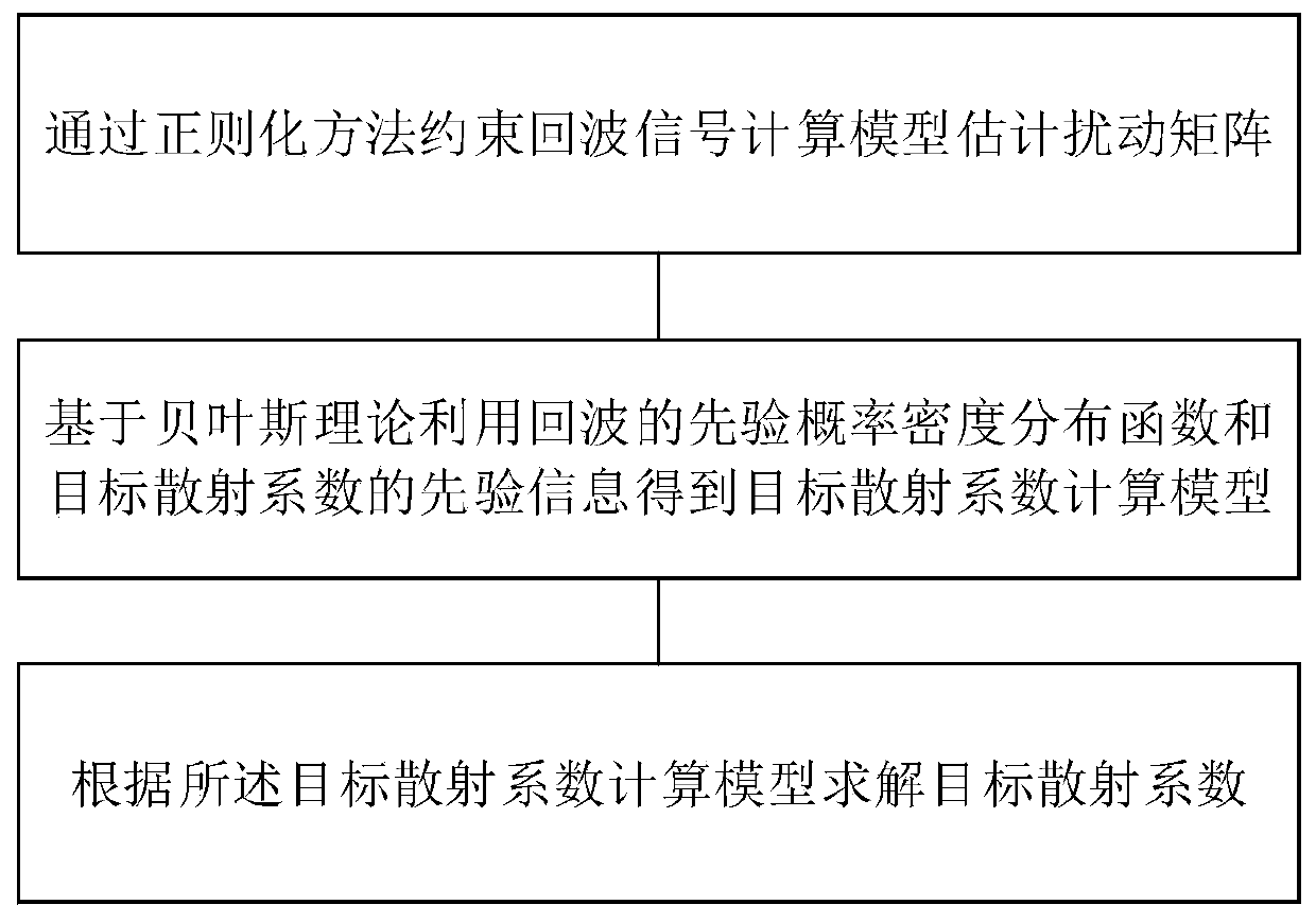
The invention discloses a Bayesian radar correlated imaging method based on disturbance matrix estimation. The method comprises a step of estimating a disturbance matrix through a regularization method constrain echo signal calculation model, a step of obtaining a target scattering coefficient calculation model by utilizing a prior probability density distribution function of an echo and prior information of a target scattering coefficient based on a Bayesian theory, and a step of solving the target scattering coefficient according to the target scattering coefficient calculation model. According to the radar correlated imaging method, the disturbance matrix is obtained through the regularization method constrain echo signal calculation model, the error of the reference matrix can be reduced due to the existence of the disturbance matrix, in addition, the target scattering coefficient calculation model is obtained according to the prior probability density distribution function and theprior information of the target scattering coefficient, the final target scattering coefficient is obtained, and therefore, the mismatch situation of the echo signal caused by the existence of the error can be effectively reduced.

Description

technical field [0001] The invention belongs to the technical field of target tracking, and in particular relates to a Bayesian radar correlation imaging method based on disturbance matrix estimation. Background technique [0002] Radar correlation imaging is derived from traditional optical imaging, which belongs to a new type of staring imaging technology. Radar correlation imaging can break through the conditions that the imaging resolution of traditional radar imaging is limited by aperture size and other conditions, and realize high-resolution imaging. Radar correlation imaging has already It has become a new development direction in the field of radar imaging. [0003] Radar correlation imaging relies on multiple independent antenna elements to transmit random signals to form a space-time two-dimensional random radiation field in space, and correlates the radiation field formed by the received scattered echo signals with the pre-stored random radiation field to obtain ...

Claims


Application Information

Patent Timeline
IPC IPC(8): G01S13/89G01S7/41
CPCG01S13/89G01S7/418
Inventor 包敏甘宜超邢孟道周静
Owner XIDIAN UNIV
Learn More