Reactor core and its reactor

A reactor and magnetic core technology, applied in the direction of transformer/inductor magnetic core, inductor, magnetic core/yoke, etc., can solve the problems of early saturation, low permeability of magnetic resin, limited improvement of yoke utilization rate, etc. Achieve the effect of avoiding premature saturation, reducing thickness, and being easy to manufacture

Active Publication Date: 2022-03-08
MOSHANG ELECTRONICS TECH SHANGHAI CO LTD
View PDF6 Cites 0 Cited by
  • Summary
  • Abstract
  • Description
  • Claims
  • Application Information

AI Technical Summary

Problems solved by technology

There are currently two methods for this kind of reactor. One is to adopt the ring reactor scheme, which has the problem of difficult winding and is not conducive to large-scale production; the other is to use block metal powder cores stacked as mouth shapes. The coil winding is wound on the center column clamped by the upper and lower yokes. This solution has the problems of insufficient space utilization and large size of the upper and lower yokes
[0003] In the patent document with the announcement number 102918610B published by the Chinese Patent Office, in order to solve this problem, a magnetic metal resin package is used to make it compact. However, since the magnetic permeability of the magnetic resin is generally low, the utilization rate of the yoke is improved. limited
In the patent document with the announcement number 102074333B published by the Chinese Patent Office, the hybrid material design is adopted, the structure is very compact, and the efficiency is also high, but there are manufacturing problems, especially for larger sizes.
The patent document with the announcement number 103714946B published by the Chinese Patent Office discloses a hybrid magnetic circuit magnetic integrated inductor, which can maintain a high coupling effect and maximize the inductance of the coil self-coupling, but there is a ferrite plate It is difficult to thin the magnetic core and there is a risk of premature saturation

Method used


Image

  • Reactor core and its reactor
  • Reactor core and its reactor
  • Reactor core and its reactor

Examples


Embodiment Construction

[0034] In order to make the above objects, features and advantages of the present invention more comprehensible, specific implementations of the present invention will be described in detail below in conjunction with the accompanying drawings.

[0035] In the following description, numerous specific details are set forth in order to provide a thorough understanding of the present invention. However, the present invention can be implemented in many other ways different from those described here, and those skilled in the art can make similar extensions without violating the connotation of the present invention, so the present invention is not limited by the specific implementations disclosed below.

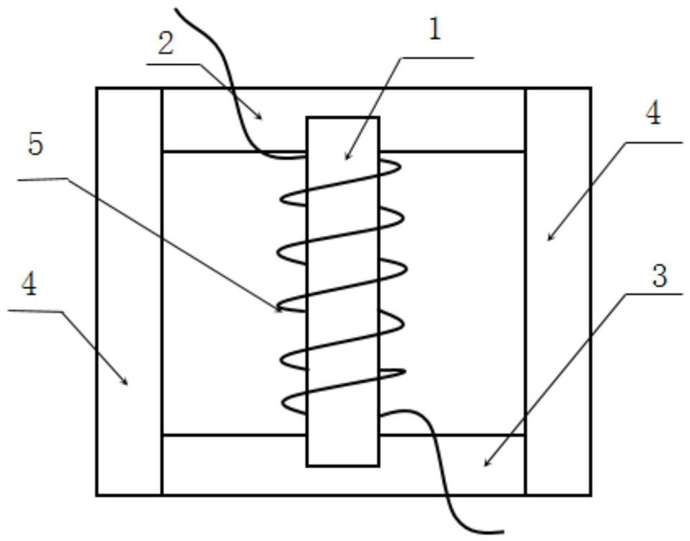
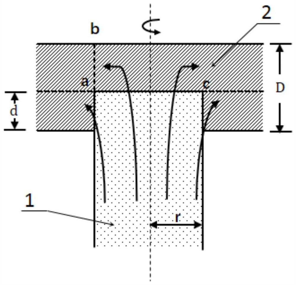
[0036] In one embodiment, see figure 1 , The reactor magnetic core includes a central column 1 , an upper yoke 2 , a lower yoke 3 and at least two side columns 4 with high magnetic permeability. Of course, if the coil 5 is wound outside the central column 1, it can become a reactor...


PUM


Abstract

A reactor magnetic core and a reactor thereof, the reactor magnetic core includes a central column (1), an upper yoke (2), a lower yoke (3) and at least two high magnetic permeability side columns (4); The center column (1) is arranged between the middle area of ​​the upper yoke (2) and the middle area of ​​the lower yoke (3), the center column (1) is used for winding the coil (5), and the The saturation magnetic flux density of the middle column (1) is greater than the saturation magnetic flux density of the upper yoke (2) and the lower yoke (3); the at least two high magnetic permeability side columns (4) are arranged at intervals between the Between the upper yoke (2) and the lower yoke (3), and the two ends of each high magnetic permeability side column (4) are connected with the outer edge of the upper yoke (2) and the lower yoke (3) respectively. ) of the outer edge connection. The reactor magnetic core and the reactor thereof improve the utilization rate of the yoke, have a compact structure and are simple to manufacture.

Description

technical field [0001] The invention relates to the technical field of reactors, in particular to a reactor magnetic core and a reactor thereof. Background technique [0002] With the development of new energy technology and electric vehicles, the demand for various reactors such as boost reactors for photovoltaic inverter circuits, inverter output reactors, and boost reactors for main power batteries of electric vehicles has become strong. As the switching frequency of power semiconductor devices continues to increase, traditional silicon steel sheet reactors have become unsuitable due to large losses, and have been replaced by metal powder core reactors represented by iron-silicon and sendust. There are currently two methods for this kind of reactor. One is to adopt the ring reactor scheme, which has the problem of difficult winding and is not conducive to large-scale production; the other is to use block metal powder cores stacked as mouth shapes. The coil winding is wou...

Claims


Application Information

Patent Timeline
Patent Type & Authority Patents(China)
IPC IPC(8): H01F27/24
CPCH01F3/10H01F2003/106H01F3/14H01F37/00H01F27/38H01F27/24H01F27/28
Inventor 黄智褚江端悦涛姜桂林
Owner MOSHANG ELECTRONICS TECH SHANGHAI CO LTD
Why Eureka
Try Eureka