Microfluidic chip and kit for detecting high-sensitive troponin

A microfluidic chip and chip technology, applied in the field of medical testing, can solve problems such as difficult to achieve sensitivity and precision, long centrifugation time, etc., and achieve high liquid mixing efficiency, high precision, and high batch-to-batch precision Effect

Active Publication Date: 2020-02-11
SHANGHAI IGENETEC DIAGNOSTICS CO LTD +1
View PDF18 Cites 6 Cited by
  • Summary
  • Abstract
  • Description
  • Claims
  • Application Information

AI Technical Summary

Problems solved by technology

However, due to the long centrifugation time required, it is difficult to meet the requirements of sensitivity and precision when it is used in the quantitative detection of high-sensitivity troponin

Method used


Image

  • Microfluidic chip and kit for detecting high-sensitive troponin
  • Microfluidic chip and kit for detecting high-sensitive troponin
  • Microfluidic chip and kit for detecting high-sensitive troponin

Examples


preparation example Construction

[0076] The preparation method of the high-sensitivity troponin detection kit of the present invention comprises the following steps:

[0077] 1) Preparation of the antibody-fluorescent microsphere labeling complex: Add cardiac troponin T monoclonal antibody to the activated fluorescent microsphere solution, mix well, add quencher and blocking agent, and centrifuge to wash;

[0078] 2) Preparation of microfluidic chip: i) Etch the sample fluid channel on the double-sided adhesive layer by laser, and reduce the width of the flow channel at the corner where the flow channel detection area and the waste liquid tank area meet during etching, making it smaller than the flow channel The width of the arc section in the middle of the flow channel in the detection area; ii) Prepare the sample injection hole treatment solution, spray it on the sample injection hole on the lower layer of the chip, and dry it; iii) Prepare the spotting reagent; iv) Spot the prepared sample spotting reagent ...

Embodiment 1

[0093] Example 1 Preparation of microfluidic chip

[0094] 1. Prepare the three-layer structure of the chip

[0095] The upper layer and the lower layer of the chip are prepared by using a mold, and the double-sided adhesive layer is etched by a laser engraving machine to obtain the middle layer of the chip.

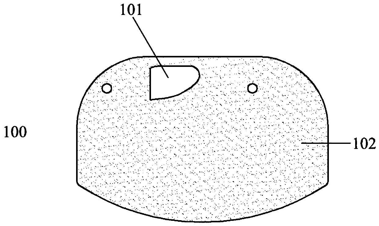
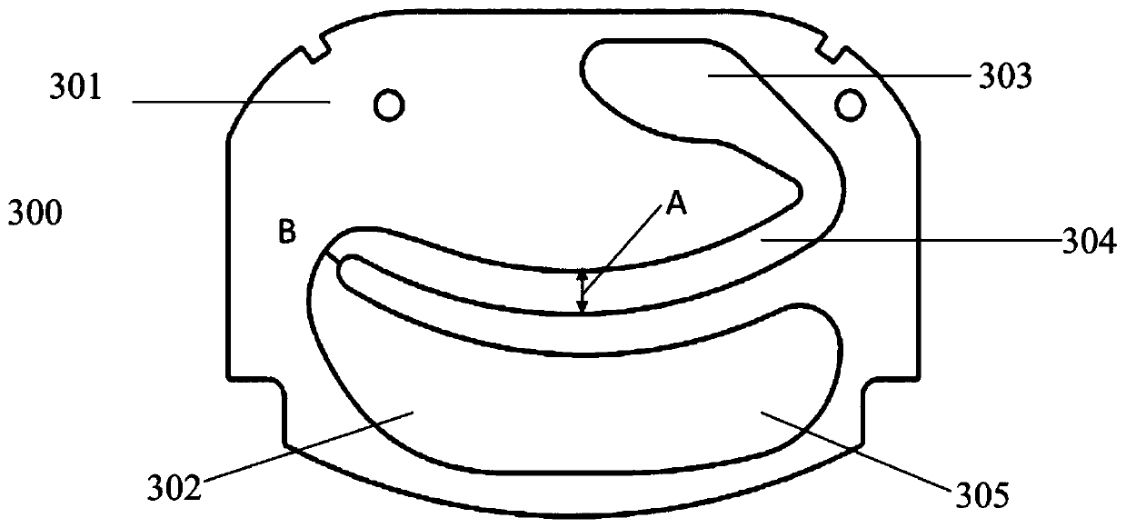
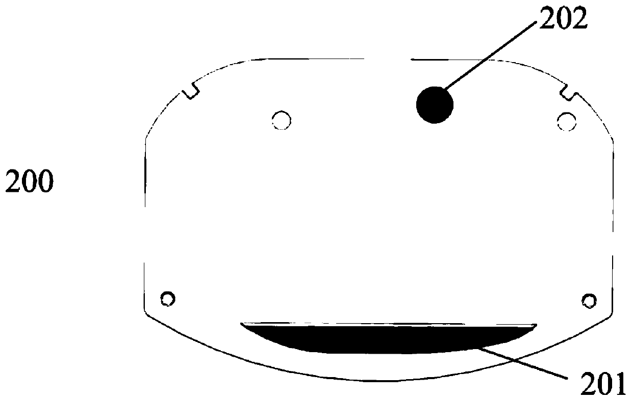
[0096] Such as Figure 1-3 As shown, the microfluidic chip used in Example 1 includes the following three-layer structure: a chip upper layer 100 , a chip lower layer 200 , and a chip middle layer 300 .

[0097] The material of the upper layer 100 of the chip is PMMA, the shape is almost oval, and the thickness of the upper layer 100 is 2.0 mm. Such as figure 1 As shown, the chip upper layer 100 includes a sample application area 101, and the shape of the sample application area 101 is an irregular sector. The upper layer of the chip has two surfaces, wherein the surface 102 in contact with the liquid sample is a frosted surface with an average surface roughness Ra ...


PUM

PropertyMeasurementUnit
Particle sizeaaaaaaaaaa
Thicknessaaaaaaaaaa

Abstract

The invention relates to a microfluidic chip and a kit for detecting high-sensitive troponin. The microfluidic chip includes three layers which are overlapped with each other, wherein the upper chip layer includes a sampling area; a groove is formed in the lower chip layer; the middle chip layer comprises a double-sided adhesive layer; a sample flowing channel is divided on the double-sided adhesive layer by using an adhesive area and an adhesive-free area; the sample flowing channel comprises a flow channel detection area; the flow channel detection area is arc; and the width of a flow channel of a turning part which is formed by crossly connecting the flow channel detection area and a waste liquid tank area is less than the width of the flow channel middle arc section of the flow channeldetection area. According to the microfluidic chip and the kit for detecting the high-sensitive troponin disclosed by the invention, through a microfluidic technology, the performance of immunochromatographic assay reagents is further promoted, and a quantitative detection system of the high-sensitive troponi with high analysis sensitivity and high accuracy can be obtained.

Description

technical field [0001] The invention belongs to the field of medical detection, and in particular relates to a microfluidic chip and a kit for detecting high-sensitivity troponin. Background technique [0002] Troponin (cTn) is currently the gold marker for the diagnosis of myocardial infarction and risk stratification for acute coronary syndrome (ACC). The sensitivity and precision of traditional cTn detection methods are relatively low, it is difficult to be detected, and it is basically impossible to detect them in apparently healthy people. When ischemic symptoms or ECG changes are not typical, this may lead to delayed diagnosis or even misdiagnosis, which is not conducive to Early diagnosis, risk assessment and prognosis. [0003] In recent years, with the advent and clinical application of various high-sensitivity troponin (hs-cTn) quantitative detection systems, on the one hand, it provides a basis for earlier clinical diagnosis of AMI and identification of more pati...

Claims


Application Information

Patent Timeline
IPC IPC(8): B01L3/00G01N33/68
CPCB01L3/502707G01N33/6893
Inventor 方雪恩刘丽玲吴静钱江洪孔继烈
Owner SHANGHAI IGENETEC DIAGNOSTICS CO LTD
Why Eureka
Try Eureka