Device and method for repairing soil and preventing pollutant diffusion
A technology for soil remediation and pollutants, which is applied in the field of soil remediation and prevents the spread of pollutants. It can solve the problems of high engineering cost, change of soil physical and chemical properties, and long cycle, so as to improve removal efficiency, prevent pollution from spreading, and have a simple structure. Effect
- Summary
- Abstract
- Description
- Claims
- Application Information
AI Technical Summary
Problems solved by technology
Method used
Image
Examples
Embodiment 1
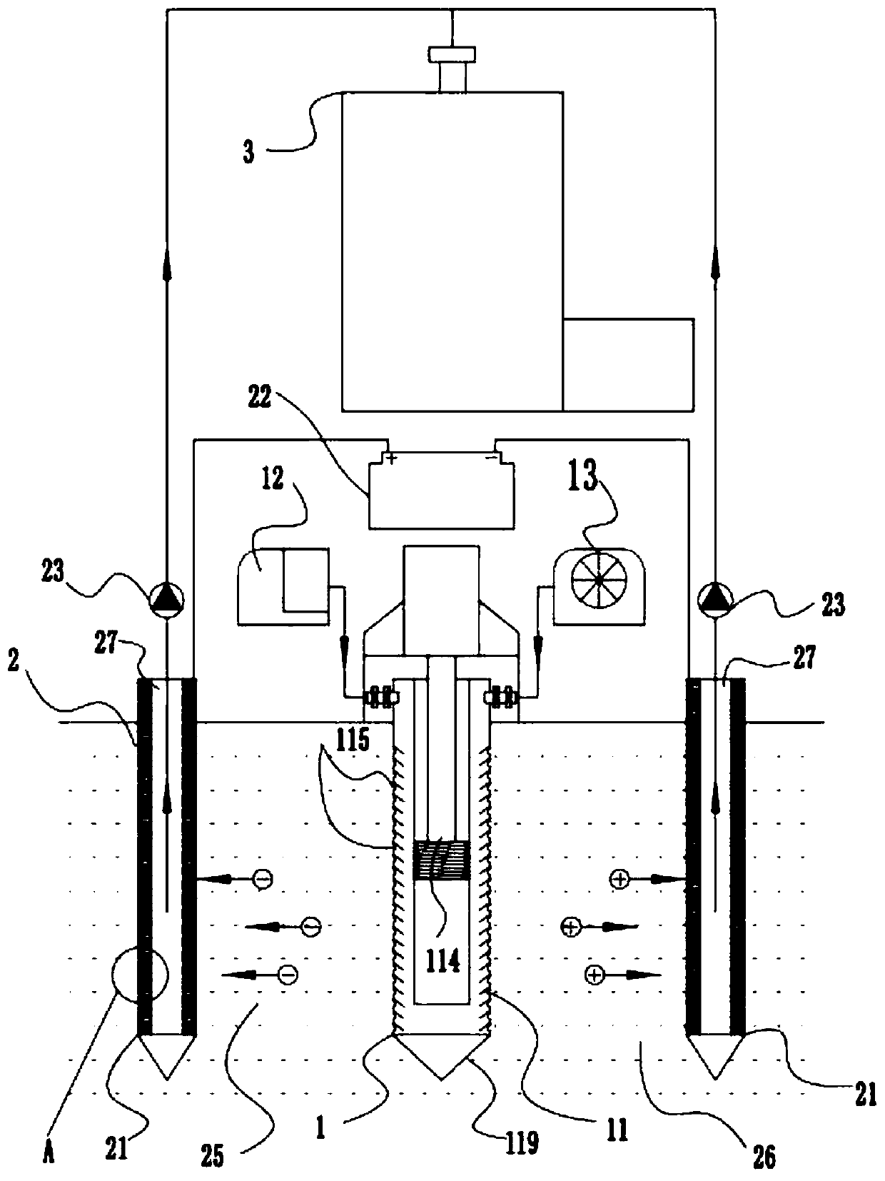
[0035] Such as Figure 9 As shown, a device for soil remediation and preventing the diffusion of pollutants, the device includes an in-situ injection pressure component 1, an electrode dialysis component 2 and a post-treatment component 3;
[0036] The in-situ injection pressure assembly 1 includes an injection pressure pipe 11 drilled in the contaminated soil area, and an atomizer 12 for generating hydrogen peroxide dry mist. The atomizer 12 can be Metso brand, the model is DF- MX atomized hydrogen peroxide sterilizer, the average spray particle size is 7.5μm, and the spray volume is 2.4L / h. And the plasma generator 13 used to generate plasma air, the plasma generator 13 is a low-temperature plasma air device capable of generating no higher than 60°C, the atomizer 12 and the plasma generator 13 are respectively arranged on the top of each injection pressure pipe 11 The inlet one 111 and the inlet two 112 are connected, and the inlet one 111 and the inlet two 112 are respecti...
Embodiment 2
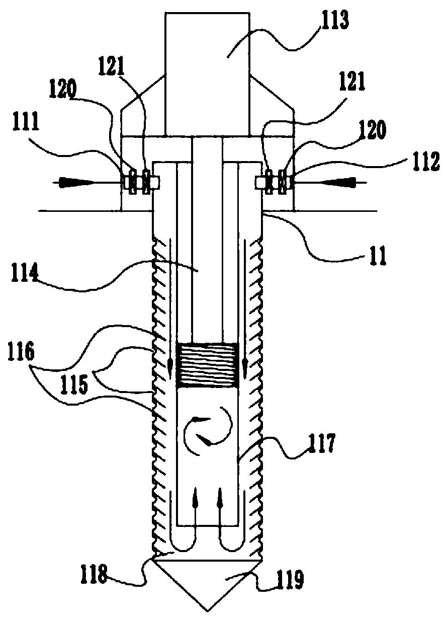
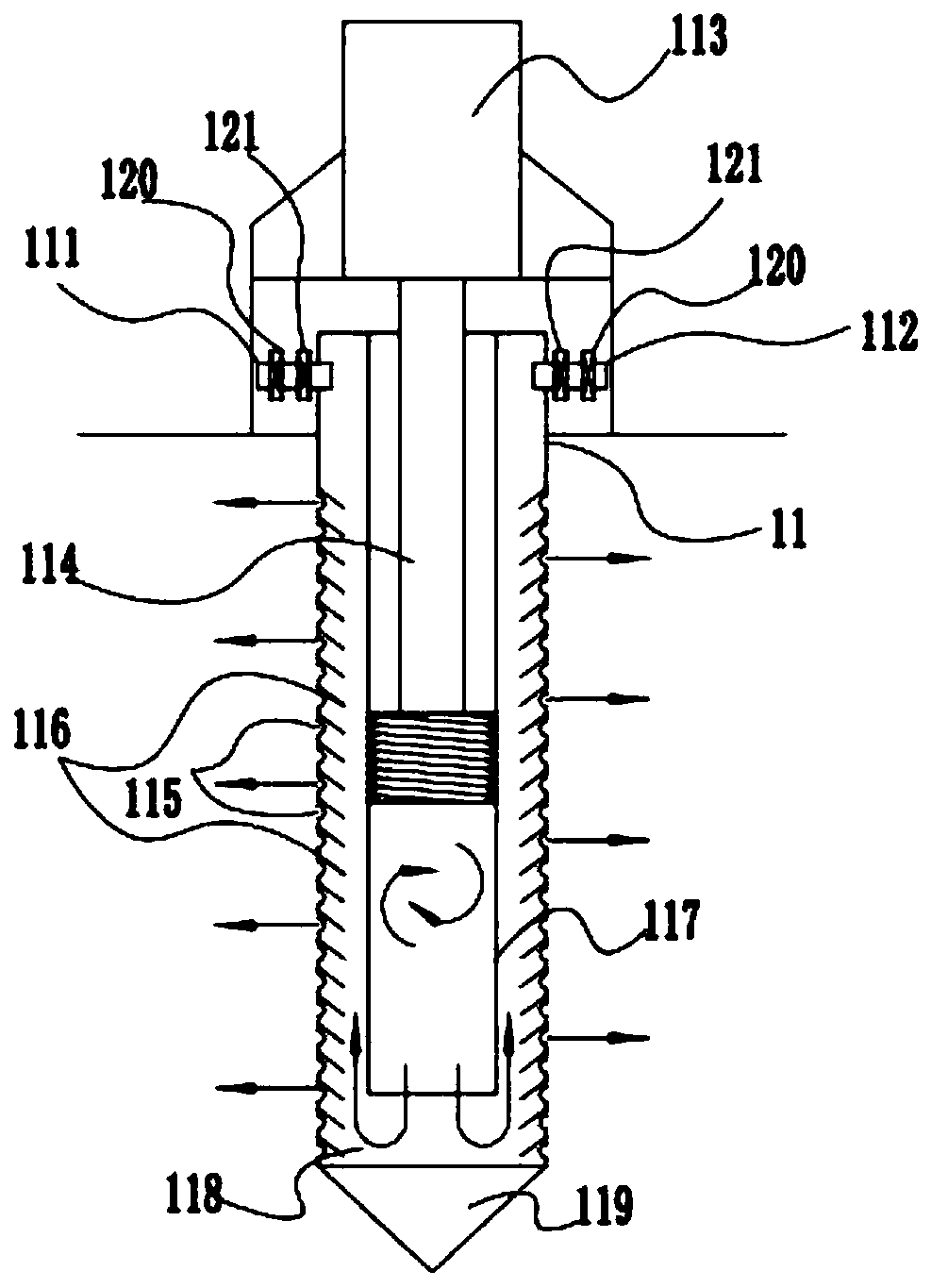
[0045] As an optimization scheme, this embodiment is basically the same as Embodiment 1, the difference is that, as Figure 4 As shown, the inside of the injection pressure tube 11 is provided with a piston inner cylinder 117 that is convenient for the movement of the piston rod 114. The upper end of the piston inner cylinder 117 is fixedly connected with the inner top of the injection pressure tube 11, and the lower end of the piston inner cylinder 117 is far from the bottom of the injection pressure tube 11. 20cm, used to communicate with the piston inner cylinder 117 and the injection tube 11 to form an injection mixing chamber 118, and the bottom of the injection tube 11 is also provided with a conical head 119 for easy drilling.
Embodiment 3
[0047] As an optimization scheme, this embodiment is basically the same as Embodiment 2, the difference is that, as figure 1 , 2 , 3, the inner wall of the injection pressure pipe 11 is provided with a plurality of baffles 116 with their ends facing down and forming an angle of 45 degrees with the inner wall of the injection pressure pipe 11. above, when the air intake as figure 2 As shown, when the intake air is from top to bottom, it is the exhaust hole 115 to block the flow, and when the air is discharged, it is as follows: image 3 As shown, the exhaust hole 115 guides the flow when exhausting from bottom to top. It can facilitate the uniform diffusion of mixed oxides and improve their utilization.
PUM
 Abstract
Description
Claims
Application Information
 - R&D
- Intellectual Property
- Life Sciences
- Materials
- Tech Scout
- Unparalleled Data Quality
- Higher Quality Content
- 60% Fewer Hallucinations
Browse by: Latest US Patents, China's latest patents, Technical Efficacy Thesaurus, Application Domain, Technology Topic, Popular Technical Reports.
© 2025 PatSnap. All rights reserved.Legal|Privacy policy|Modern Slavery Act Transparency Statement|Sitemap|About US| Contact US: help@patsnap.com


