Compressed air heat exchange system
A technology of heat exchange system and compressed air, which is applied in the direction of compressors, irreversible cycle compression machines, and reversible cycle compression machines, etc., which can solve environmental hazards and other problems, achieve reduced production costs, reliable system operation, and long life Effect
- Summary
- Abstract
- Description
- Claims
- Application Information
AI Technical Summary
Problems solved by technology
Method used
Image

Examples
Embodiment 1
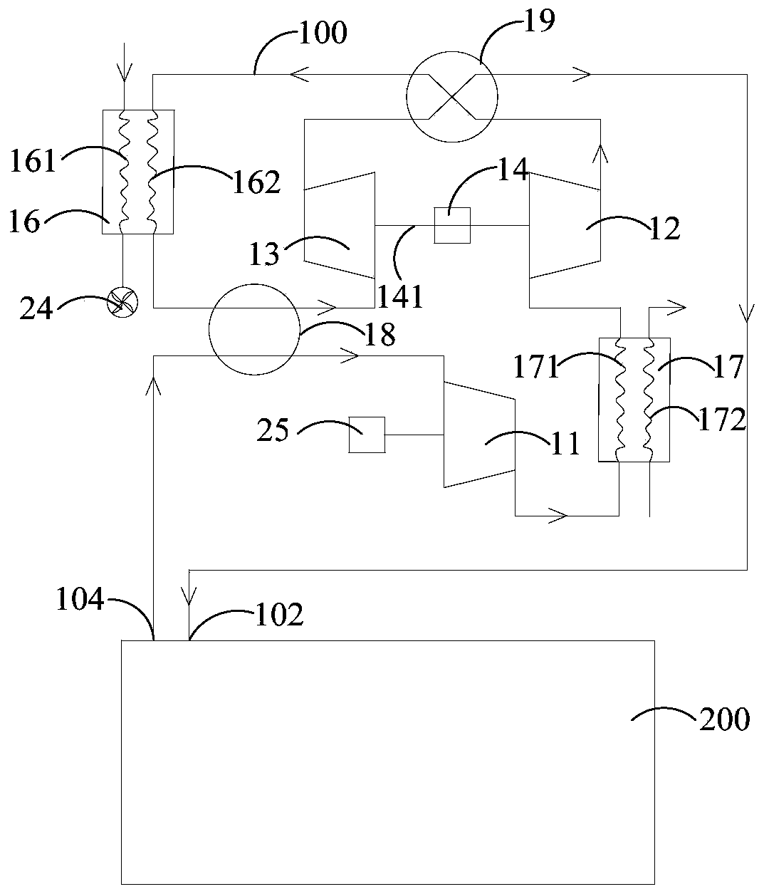
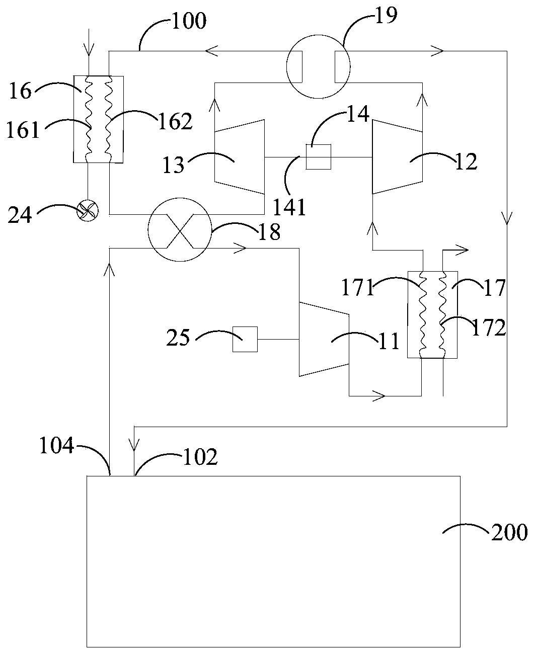
[0068] A compressed air heat exchange system includes: an air refrigeration flow path 100 . Such as figure 1 and figure 2 As shown, the air refrigeration flow path 100 is provided with a first compressor 11 , a second compressor 12 , and an expander 13 . The first compressor 11 and the second compressor 12 are used to increase the temperature and pressure of the air flowing through the air cooling flow path 100 . The expander 13 is used for reducing the temperature and pressure of the air flowing through the air cooling flow path 100 . The inlet and outlet of the air cooling flow path 100 respectively form the air return port 104 and the air outlet port 102 of the compressed air heat exchange system.
[0069] Wherein, the expander 13 is coaxially connected with the second compressor 12 through a connecting shaft 141, such as figure 1 and figure 2 As shown, and the air inlet of the second compressor 12 communicates with the air outlet of the first compressor 11 .
[007...
Embodiment 2
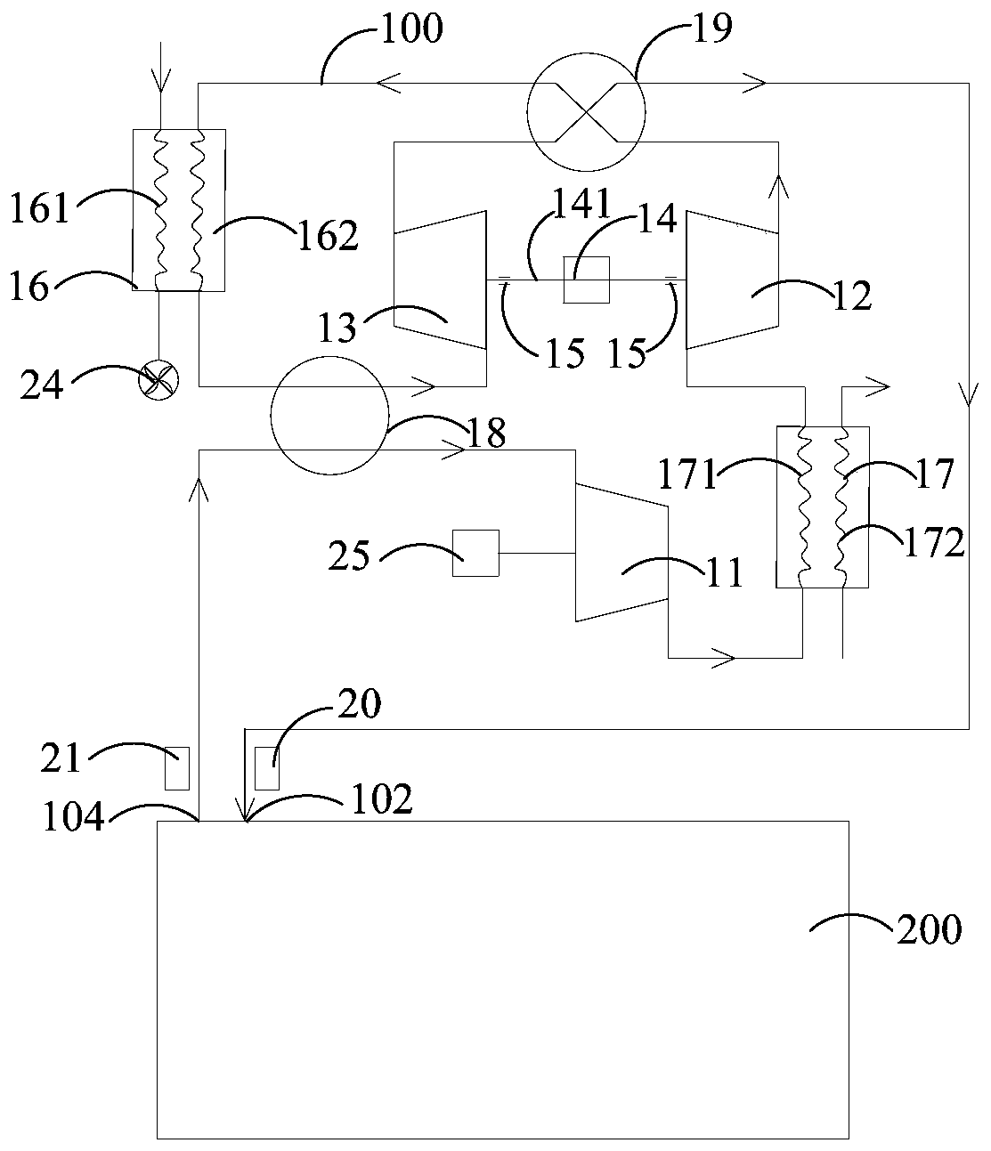
[0096] On the basis of the first embodiment, further, the connecting shaft 141 is sleeved with a dynamic pressure gas bearing 15, such as image 3 , Figure 4 and Figure 9 shown.
[0097] This solution uses the dynamic pressure gas bearing 15, relies on the high-speed relative motion between the shaft and the bearing to generate a pressure gas model with dynamic pressure lubrication, has low assembly requirements, resists rotor misalignment, and has good stability at high speed. Compared with static pressure gas bearings and magnetic suspension bearings, the structure is simpler, the cost is lower, and it is more suitable for household air conditioners.
[0098] Specifically, such as Figure 10 and Figure 11 As shown, the dynamic pressure gas bearing 15 includes a corrugated foil type foil bearing, and the corrugated foil type foil bearing includes: a bearing seat 151 and multi-layer foils. The inner wall of the bearing seat 151 defines a fixing groove. The multi-layer...
Embodiment 3
[0105] Embodiment three (not shown in the figure)
[0106] The difference from Embodiment 1 is that the first control valve 18 includes: a first one-way valve, a second one-way valve, a third one-way valve and a fourth one-way valve. The second control valve 19 includes: a fifth one-way valve, a sixth one-way valve, a seventh one-way valve and an eighth one-way valve.
[0107] Wherein, the first one-way valve is located between the air return port 104 and the air inlet of the expander 13 , and is used to make the air return port 104 conduct one-way to the air inlet of the expander 13 .
[0108] The second one-way valve is located between the outlet of the second control valve 19 and the inlet of the first compressor 11 , and is used for one-way communication from the outlet of the second control valve 19 to the inlet of the first compressor 11 .
[0109] The third one-way valve is located between the air return port 104 and the air inlet of the first compressor 11 , and is us...
PUM
 Abstract
Description
Claims
Application Information
 - R&D
- Intellectual Property
- Life Sciences
- Materials
- Tech Scout
- Unparalleled Data Quality
- Higher Quality Content
- 60% Fewer Hallucinations
Browse by: Latest US Patents, China's latest patents, Technical Efficacy Thesaurus, Application Domain, Technology Topic, Popular Technical Reports.
© 2025 PatSnap. All rights reserved.Legal|Privacy policy|Modern Slavery Act Transparency Statement|Sitemap|About US| Contact US: help@patsnap.com