Production and machining equipment for relief butterfly valves
What is Al technical title?
Al technical title is built by PatSnap Al team. It summarizes the technical point description of the patent document.
A technology of processing equipment and butterfly valves, which is applied in metal processing equipment, drilling/drilling equipment, metal processing machinery parts, etc., can solve the problems of poor drilling quality of valves, increased physical strength of workers, and low work efficiency, and achieves Improve practicality and reliability, facilitate collection work, and improve practicality
Active Publication Date: 2020-02-14
SHANDONG ZHUCHENG JIANHUA VALVE MFG
View PDF5 Cites 8 Cited by
Summary
Abstract
Description
Claims
Application Information
AI Technical Summary
This helps you quickly interpret patents by identifying the three key elements:
Problems solved by technology
Method used
Benefits of technology
Problems solved by technology
[0002] As we all know, the valve is the main control component in the pipeline transportation system, among which the decompression butterfly valve is widely used. The decompression butterfly valve needs to be punched during production and processing. The existing punching method is mainly to The valve is fixed on the operating table, and the drill bit installed on the drilling equipment is used to drill the hole. However, the existing drilling equipment cannot move laterally. When drilling other positions on the valve, the valve needs to be repositioned. And fixed, the operation is more cumbersome, the drilling time is longer, which greatly increases the physical strength consumed by the workers, and the work efficiency is low. At the same time, the valve positioning is carried out by human eye observation, the positioning accuracy is poor, and the valve drilling quality is poor.
Method used
Image
Click on the blue label to locate the original text in one second.
Reading with bidirectional positioning of images and text.
Examples
Embodiment Construction
[0018] The specific implementation manners of the present invention will be further described in detail below in conjunction with the accompanying drawings and embodiments. The following examples are used to illustrate the present invention, but are not intended to limit the scope of the present invention.
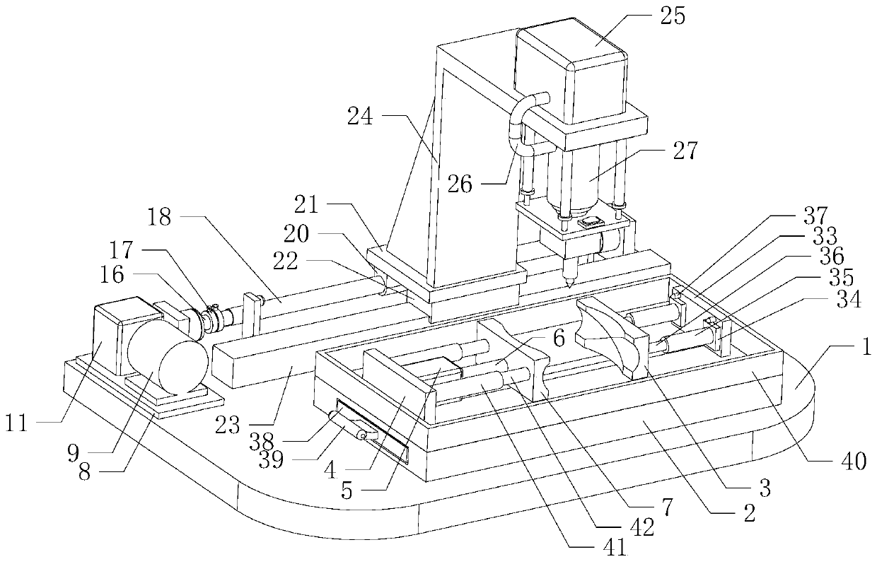
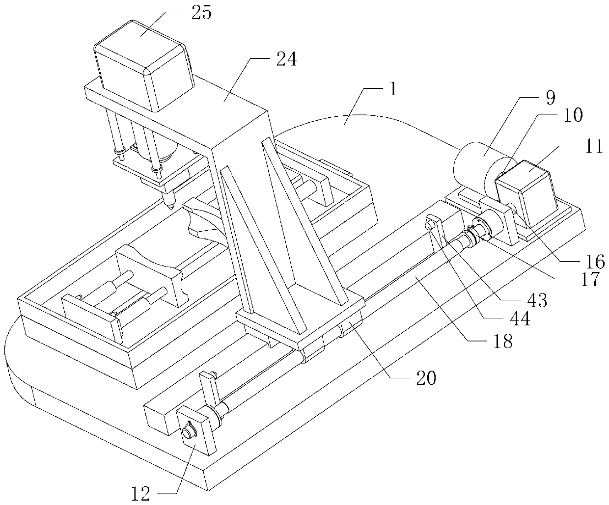
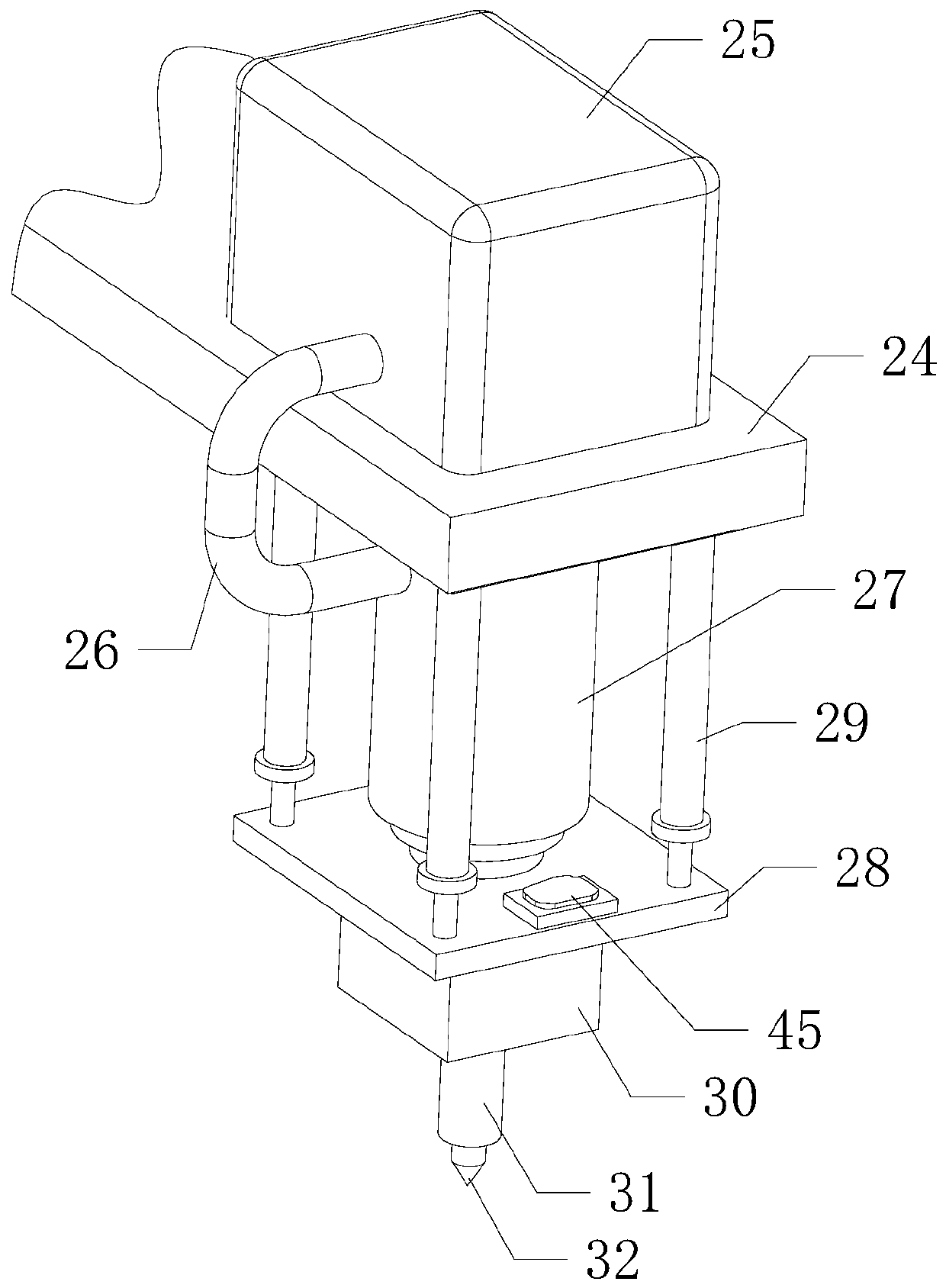
[0019] Such as Figure 1 to Figure 4 As shown, a kind of decompression butterfly valve production and processing equipment of the present invention, when it is working, first the valve is placed between the positioning plate 3 and the clamping plate 7, the right end of the valve and the inner wall of the fixing groove on the positioning plate 3 Contact, open the cylinder 5, the cylinder 5 pushes the push rod 6 and the clamping plate 7 to move to the right, the inner wall of the fixing groove on the clamping plate 7 contacts the left end of the valve and squeezes and clamps the valve, wherein the positioning plate 3 can Quickly locate the valve, open the second motor 30, t...
PUM
Abstract
The invention relates to the technical field of mechanical equipment, in particular to production and machining equipment for relief butterfly valves. The production and machining equipment comprisesa base, a workbench, a positioning plate, a first mounting plate, an air cylinder, a pushing rod, a clamping plate, a motor seat, a first motor, a first rotating shaft and a speed reducer, wherein thebottom end of the workbench is mounted on the front side of the top end of the base, an adjusting device is arranged on the right side of the top end of the workbench, the left end of the adjusting device is connected with the right end of the positioning plate, and the bottom end of the positioning plate is contacted with the top end of the workbench. According to the production and machining equipment for the relief butterfly valves, punching operation is carried out on the different positions on the valves, so that a punching process of the valves is effectively simplified, the punching time is shortened, the time and physical force for manually positioning the valves multiple times are saved, and the working efficiency is improved; and meanwhile, the position of a drill bit is precisely controlled, so that the position precision of a valve hole is effectively improved, the machining quality of the valves is improved, and the practicability and the reliability are improved.
Description
technical field [0001] The invention relates to the technical field of mechanical equipment, in particular to a production and processing equipment for a decompression butterfly valve. Background technique [0002] As we all know, the valve is the main control component in the pipeline transportation system, among which the decompression butterfly valve is widely used. The decompression butterfly valve needs to be punched during production and processing. The existing punching method is mainly to The valve is fixed on the operating table, and the drill bit installed on the drilling equipment is used to drill the hole. However, the existing drilling equipment cannot move laterally. When drilling other positions on the valve, the valve needs to be repositioned. And fixed, the operation is more cumbersome, the drilling time is longer, which greatly increases the physical strength of the workers, and the work efficiency is low. At the same time, the valve positioning is carried ...
Claims
Application Information
Patent Timeline
Application Date:The date an application was filed.
Publication Date:The date a patent or application was officially published.
First Publication Date:The earliest publication date of a patent with the same application number.
Issue Date:Publication date of the patent grant document.
PCT Entry Date:The Entry date of PCT National Phase.
Estimated Expiry Date:The statutory expiry date of a patent right according to the Patent Law, and it is the longest term of protection that the patent right can achieve without the termination of the patent right due to other reasons(Term extension factor has been taken into account ).
Invalid Date:Actual expiry date is based on effective date or publication date of legal transaction data of invalid patent.