
A time-based phase-controlled DC stabilized power supply

A DC stabilized power supply and phase control technology, applied in the direction of adjusting electrical variables, control/regulation systems, instruments, etc., can solve problems such as high cost, reliability, and poor stability, and achieve good consistency of parameters and improved reliability , the effect of cost reduction

Active Publication Date: 2020-09-18
SCHOLAR HOME SHANGHAI NEW MATERIAL CO LTD
View PDF5 Cites 0 Cited by
  • Summary
  • Abstract
  • Description
  • Claims
  • Application Information

AI Technical Summary

Problems solved by technology

[0006] The technical problem to be solved by the present invention is to provide a time-based phase-controlled DC regulated power supply, which solves the problems of poor reliability, stability and high cost of the phase-controlled DC regulated power supply in the prior art

Method used


Image

  • A time-based phase-controlled DC stabilized power supply
  • A time-based phase-controlled DC stabilized power supply

Examples


specific Embodiment

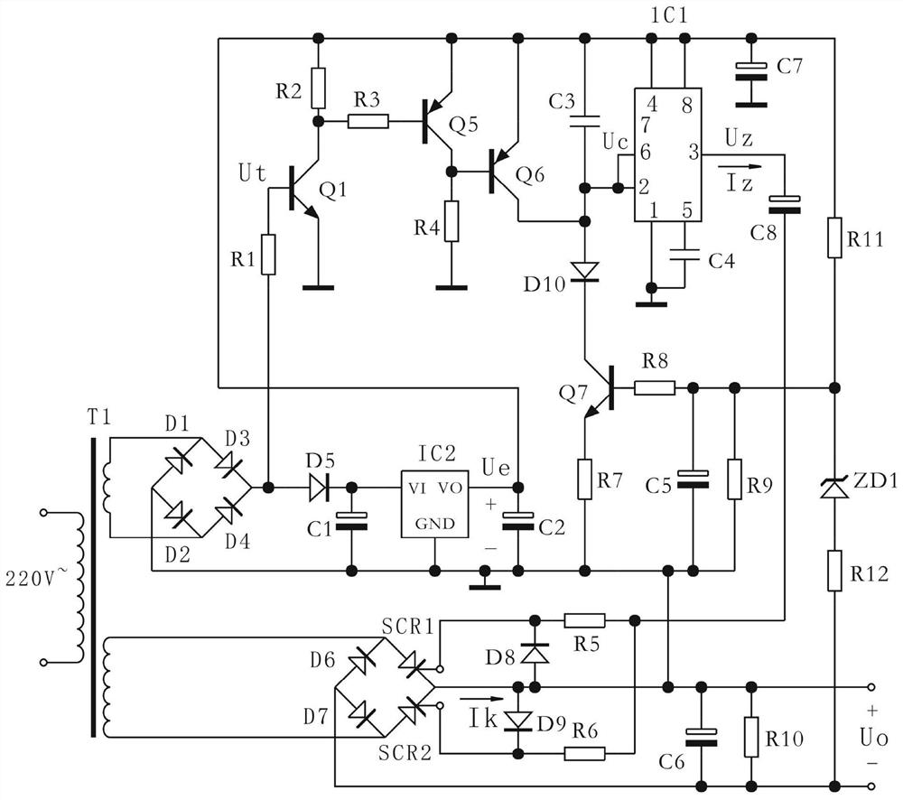
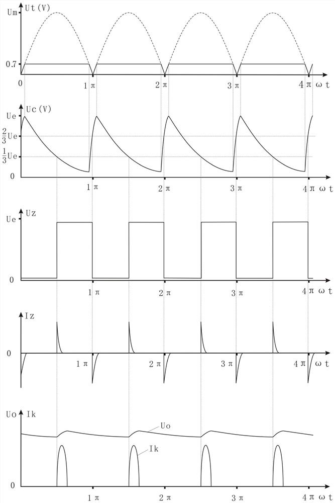
[0034] Specific examples, such as figure 1 , figure 2 Shown:

[0035] The trigger is composed of 555 time base chip IC1; the phase-controlled silicon controlled rectifier is composed of SCR1 and SCR2; the trigger synchronous switch is mainly composed of transistors Q1, Q5, Q6, among which Q1 is the trigger synchronous switch input tube, and Q6 is the trigger synchronous switch output The delay capacitor is composed of C3; the trigger control circuit is mainly composed of crystal transistor Q7 and Zener diode ZD1; the phase-controlled synchronous signal source is composed of AC power transformer T1 and crystal diodes D1, D2, D3, D4; the trigger circuit power supply Ue It is mainly composed of IC2.

[0036] Among them, the ground terminal 1 of the 555 chip IC1 is connected to the cathode of the phase-controlled thyristor SCR1, SCR2 and the positive pole Uo+ of the phase-controlled DC power supply, so that the cathode of the phase-controlled thyristor is at the same potential ...


PUM


Abstract

The invention discloses a time-base phase-control direct-current stabilized power supply which is mainly composed of a trigger, a phase-control silicon controlled rectifier, a trigger synchronous switch, a delay capacitor, a trigger control circuit, a phase-control synchronous signal source and a trigger circuit power supply. The trigger selects a 555 time-base integrated circuit chip with excellent performances and low price and is specifically connected with the phase-controlled silicon controlled rectifier, the trigger synchronous switch, the delay capacitor, the trigger control circuit andthe phase-control synchronous signal source to form a unique time-base phase-controlled trigger circuit. Compared with the existing phase-control direct-current voltage-stabilizing power supply, thetime-base phase-control direct-current stabilized power supply has a simple structure because of avoidance of a complex discrete component circuit and a single-chip microcomputer control system and has advantages of great anti-interference capability and high working stability and reliability. Because of the simple structure, the core component 555 chip is low in price and the cost of the phase control trigger circuit is greatly reduced.

Description

technical field [0001] The invention belongs to the field of electronic technology phase-controlled DC stabilized voltage power supply, in particular to a time-base phase-controlled DC stabilized voltage power supply. Background technique [0002] There are two types of phase-controlled trigger circuits in existing phase-controlled DC stabilized power supplies, namely discrete and integrated. [0003] The discrete type has poor reliability and stability, complex phase control circuit, difficult adjustment, and high power consumption. [0004] Although the modular integrated type has better performance, it is expensive and mostly depends on imports. [0005] The existing phase-controlled DC stabilized power supply cannot meet the requirements of excellent performance and low price. Contents of the invention [0006] The technical problem to be solved by the present invention is to provide a time-based phase-controlled DC regulated power supply, which solves the problems o...

Claims


Application Information

Patent Timeline
Patent Type & Authority Patents(China)
IPC IPC(8): G05F1/567
CPCG05F1/567
Inventor 段卫斌卞京毕盈盈
Owner SCHOLAR HOME SHANGHAI NEW MATERIAL CO LTD
Learn More