Controllable multi-point active fluid heat dissipation system integrated on PCB

A heat dissipation system and active technology, applied in the direction of circuit fluid transportation, electric solid devices, circuit heat devices, etc., can solve the problems of low integration, limited pump cavity compression ratio, weak control ability of fluid heat dissipation system, etc., to achieve flexible structure, The effect of changing the form and improving the degree of integration

Active Publication Date: 2020-02-18
CHONGQING UNIV
View PDF14 Cites 7 Cited by
  • Summary
  • Abstract
  • Description
  • Claims
  • Application Information

AI Technical Summary

Problems solved by technology

However, it does not disclose how to efficiently integrate fluid pumps with PCB substrates and microchannel heat sinks.
In addition, the structure of the single piezoelectric single crystal actuator adopted by the fluid pump limits the compression ratio of the pump cavity, and the improvement of the pump flow rate is also limited. When the system has multiple cooling points, the fluid pump cannot provide high-power Electronic component heat dissipation provides greater flow
[0004] Since scholars from various countries have not proposed an effective solution on how to integrate the fluid pump with the microchannel heat sink and other components, the mainstream fluid cooling system has the problems of weak control ability and low integration level, and for complex subdivisions on the PCB There are also problems in how to effectively dissipate the local hot spots generated when they work

Method used


Image

  • Controllable multi-point active fluid heat dissipation system integrated on PCB
  • Controllable multi-point active fluid heat dissipation system integrated on PCB
  • Controllable multi-point active fluid heat dissipation system integrated on PCB

Examples


Embodiment Construction

[0053] The present invention is described in detail below in conjunction with accompanying drawing and embodiment:

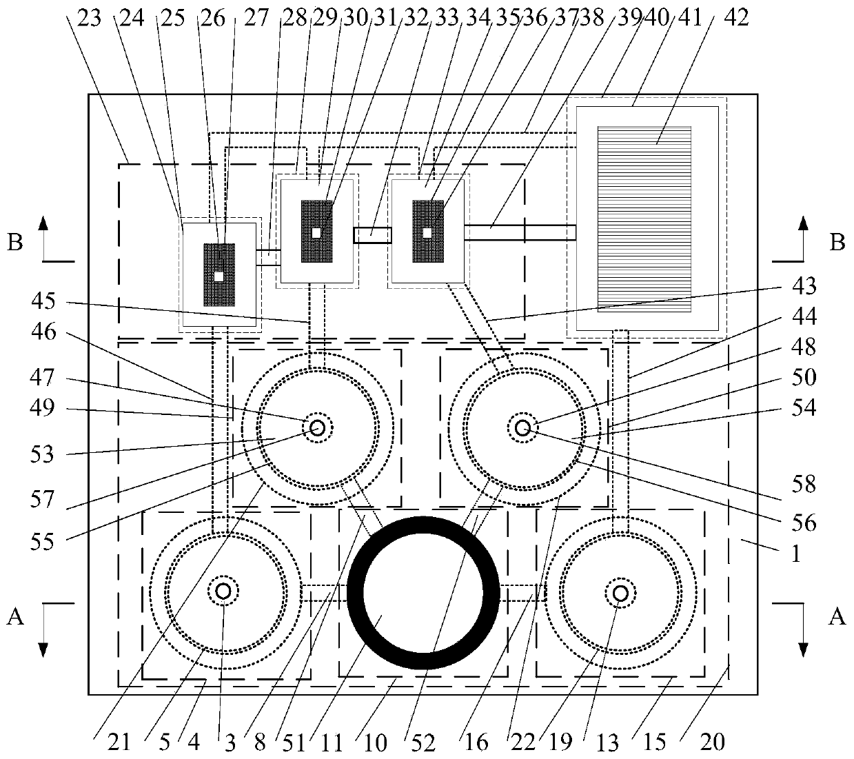
[0054] figure 1 It is a schematic diagram of the structure and principle of the controllable active fluid cooling system integrated on the PCB of this embodiment. The controllable active fluid cooling system integrated on the PCB is composed of an active fluid control device 20 , a cooling device 23 and a fluid cooling device 40 welded on the PCB substrate 1 . Wherein the active fluid control device 20 is mainly composed of a piezoelectric actuated fluid pump consisting of a cylindrical pump action unit 10 and a plurality of piezoelectric actuated fluid pumps with torus boundaries 3, 13, 47, 48. Fluid valves 4, 15, 49, 50 constitute, and the cylindrical pump action unit 10 communicates with a plurality of piezo-actuated fluid valves 4, 15, 49, 50 with torus boundaries through flow channels 8, 16, 51, 52 connect. Among them, the cylindrical pump action unit 10...


PUM


Abstract

The invention discloses a controllable multi-point active fluid heat dissipation system integrated on a PCB. The active fluid heat dissipation system is composed of an active fluid control device, a heat dissipation device and a fluid cooling device. All the devices are integrated on a PCB. The active fluid control device is mainly composed of a plurality of active control piezoelectric fluid valves and piezoelectric fluid pumps, wherein the active control piezoelectric fluid valves and the piezoelectric fluid pumps are integrated on a PCB and provided with annular surface boundaries. The heatdissipation device is mainly composed of a plurality of micro-channel heat sinks, electronic devices subjected to heat dissipation are placed above the micro-channel heat sinks respectively, and heatflow sensors are placed above the electronic devices respectively. The liquid cooling device is mainly composed of a liquid storage pool and heat dissipation fins or refrigeration pieces. The systemis suitable for being integrated on the PCB, can efficiently and continuously dissipate heat of a plurality of electronic components at different positions and in different areas on the PCB, and has the function of precisely controlling the flow rate, the flow velocity and the flow direction of fluid so as to achieve the purpose of realizing heat management of high-power and high-heat-flux electronic components.

Description

technical field [0001] The invention belongs to the technical field of controllable microfluid thermal management, and in particular relates to the integrated technology of an active fluid cooling system on a PCB. Background technique [0002] The thermal management of high-power and high-heat-flux electronic components (chips) is the core of the future development of electronic devices and the key to restricting the development of electronic devices (chips). With the gradual failure of Moore's Law, the emergence of 3D integrated electronic devices (chips), and the continuous development of electronic equipment (chips) towards miniaturization and high power density, while the performance is getting higher and higher, its energy consumption and heat dissipation The problem is also becoming more and more prominent. Thermal management of electronic devices (chips) has become a key technology to ensure product performance and life. [0003] In the 20 years since Tuckerman and ...

Claims


Application Information

Patent Timeline
Patent Type & Authority Applications(China)
IPC IPC(8): H05K1/02H05K7/20H01L23/473
CPCH05K1/0272H05K1/0203H05K7/20272H05K7/20281H01L23/473
Inventor 王代华彭芸浩
Owner CHONGQING UNIV
Why Eureka
Try Eureka