Drying device used for Bundy tubes

A technology of drying equipment and Bondi tube, which is applied in the field of Bondi tube drying equipment, can solve the problems of slow dissipation of high temperature, lower heat energy utilization rate, and prolong the drying time, so as to reduce moisture and increase work Effects of Area, Acceleration, and Efficiency

Inactive Publication Date: 2020-02-21
TIANJIN HONGREN METAL MATERIAL CO LTD
View PDF0 Cites 2 Cited by
  • Summary
  • Abstract
  • Description
  • Claims
  • Application Information

AI Technical Summary

Problems solved by technology

[0004] The object of the present invention is to provide a kind of drying equipment that is used for Bondi tube, to solve the present drying equipment that is used for Bondi tube that proposes in the above-mentioned background technology is generally the form of drying box, by feeding roller and receiving The material roller passes the steel bar and dries it, but in the actual drying process, the acid solution on the steel bar is more attached, and when the steel bar is transported out of the dryer, there will still be water marks on the surface; And when drying by hot air, often when the temperature of the heating tube reaches the rated temperature, the heating tube will be closed after being detected by the temperature sensor, and the internal high temperature temperature will dissipate slowly, resulting in a greatly reduced utilization rate of heat energy; It is in a relatively static state, and water stains need to be volatilized at high temperatures, resulting in slower removal of water stains on the steel belt, which greatly prolongs the problem of drying time

Method used


Image

  • Drying device used for Bundy tubes
  • Drying device used for Bundy tubes
  • Drying device used for Bundy tubes

Examples


Embodiment Construction

[0016] The following will clearly and completely describe the technical solutions in the embodiments of the present invention with reference to the accompanying drawings in the embodiments of the present invention. Obviously, the described embodiments are only some, not all, embodiments of the present invention. Based on the embodiments of the present invention, all other embodiments obtained by persons of ordinary skill in the art without making creative efforts belong to the protection scope of the present invention.

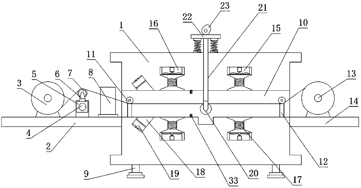
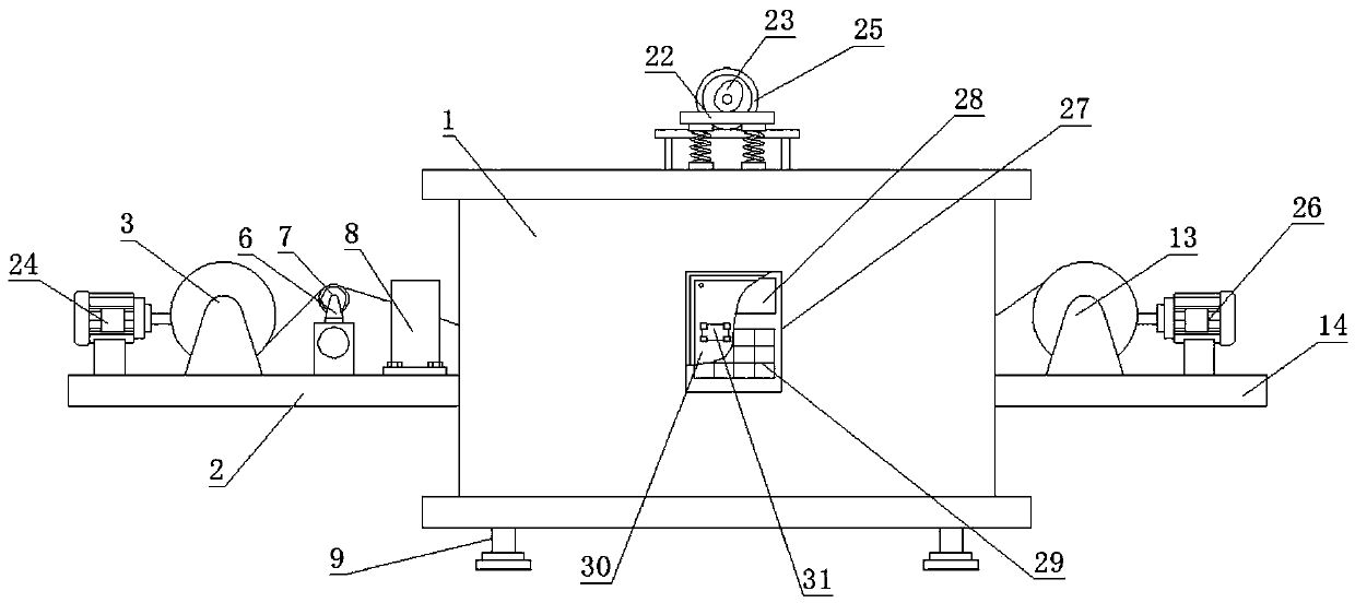
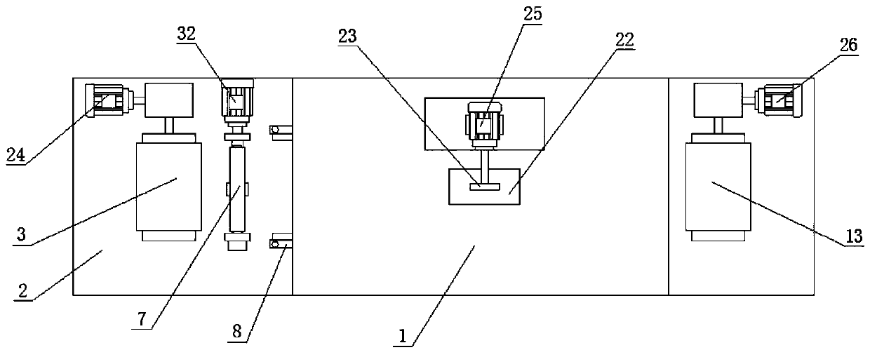
[0017] see Figure 1-4 , the present invention provides a technical solution: a drying equipment for Bondi tubes, including a body 1, a left support plate 2 is welded on the left side of the body 1, and a feeding device is installed on the left end of the upper surface of the left support plate 2 Roller 3, reducer is installed on the rotating shaft behind feed roller 3, and feed motor 24 is installed on the rotating shaft at the left end of reducer. A sliding...


PUM


Abstract

The invention discloses a drying device used for Bundy tubes. The drying device used for the Bundy tubes comprises a device body. A left supporting plate is welded to the left side face of the devicebody. A feed roller is installed at the left end of the upper surface of the left supporting plate. A speed reducer is installed on a rotary shaft and located behind the feed roller. A feed motor is installed on the rotary shaft and is located at the left end of the speed reducer. A single-rotation reciprocating lead screw is installed at the right end of the feed roller. A sliding block is installed on the side wall of the single-rotation reciprocating lead screw. According to the drying device used for the Bundy tubes, a cotton roller composed of a roller body and cotton cloth is arranged inthe feed area and can be used for wiping residual acid liquor and residual cleaning liquid on steel bars in advance to reduce residual moisture on the surfaces of the steel bars, so that the drying efficiency is greatly improved, and the situation that water stains still exist on the surfaces of the steel bars after primary drying is avoided; and the cotton roller can move back and forth under the effect of the single-rotation reciprocating lead screw and can roll when making contact and rubbing with the steel bars, so that the working area of the cotton roller is greatly enlarged, the utilization rate of the cotton roller is increased, and time-consuming and strenuous regular replacement of the cotton roller is not needed.

Description

technical field [0001] The invention belongs to the technical field of drying equipment, and in particular relates to a drying equipment for Bondi tubes. Background technique [0002] Bondi tube refers to a thin steel pipe with a diameter of 4.6 to 10.6. Generally, its surface is plated with copper molds. It is mainly used as a liquid guide and air guide tube for automobiles and refrigerators. The manufacturing process of Bondi tube is longitudinal cutting, stripping, pickling and drying , cold-rolled pipe, welding and copper plating, because after pickling, the steel bar needs to be dried to remove water stains on the surface, but the current drying equipment for Bondi pipe is still in use Few deficiencies. [0003] The current drying equipment for Bondi tubes is generally in the form of a drying box. The steel strips are passed through the feeding roller and the receiving roller and dried, but in the actual drying process, the acid on the steel strips There is a lot of l...

Claims


Application Information

Patent Timeline
Patent Type & Authority Applications(China)
IPC IPC(8): F26B13/04F26B13/14F26B13/28F26B21/00F26B21/02F26B21/10F26B25/02F26B25/04
CPCF26B13/14F26B13/28F26B21/001F26B21/02F26B21/10F26B25/02F26B25/04
Inventor 周涛刘博
Owner TIANJIN HONGREN METAL MATERIAL CO LTD
Why Eureka
Try Eureka