
Microscopic imaging objective lens for fiber core identification of optical fiber fusion splicer and imaging method thereof

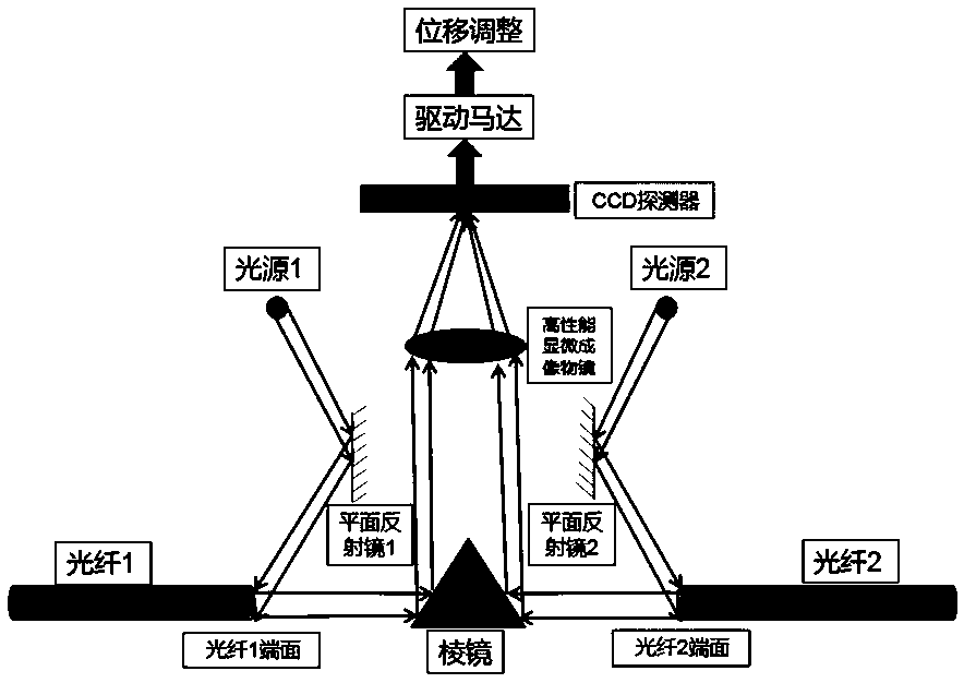
An optical fiber fusion splicing machine and microscopic imaging technology, which is applied in the direction of microscope, optical waveguide coupling, optics, etc., can solve the problems of unsatisfactory imaging performance, high difficulty, and large relative aperture, so as to ensure the efficiency and quality of fusion splicing, and ensure high Accurate alignment and reduced splice loss

Pending Publication Date: 2020-02-21
苏州信沃特光电科技有限公司
View PDF0 Cites 4 Cited by
  • Summary
  • Abstract
  • Description
  • Claims
  • Application Information

AI Technical Summary

Problems solved by technology

This high-performance microscopic imaging objective not only requires large relative aperture and high resolution; it is also required to have a high method magnification due to special application requirements; it is also required to have a large field of view due to the limitation of a specific optical path It is difficult for the objective lens to meet the requirements of field of view and large relative aperture at the same time, and it is even more difficult to obtain high magnification, and the imaging performance is difficult to meet the requirements of the core-aligned fiber fusion splicer

Method used


Image

  • Microscopic imaging objective lens for fiber core identification of optical fiber fusion splicer and imaging method thereof
  • Microscopic imaging objective lens for fiber core identification of optical fiber fusion splicer and imaging method thereof
  • Microscopic imaging objective lens for fiber core identification of optical fiber fusion splicer and imaging method thereof

Examples


Embodiment 1

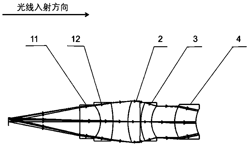
[0022] The technical solution of this embodiment is to provide a high-precision microscopic imaging objective lens for fiber core identification and alignment of an optical fiber fusion splicer. Its working band is 780-820nm, the system numerical aperture is 0.21, and the field of view is 2.5mm.

[0023] See attached figure 2 , which is the imaging optical path diagram of the microscopic imaging objective lens used for fiber core identification and alignment of the fiber fusion splicer provided by this embodiment; A meniscus spherical lens separated by blocks is formed, along the incident direction of the light, followed by a concave-convex spherical positive lens 11 of a doublet lens; a meniscus spherical negative lens 12 of a doublet lens; a double-convex spherical positive lens 2; a meniscus spherical surface Negative lens 3; meniscus spherical thick positive lens 4.

[0024] The aperture stop is located on the rear surface of the biconvex spherical positive lens 2, the f...


PUM

PropertyMeasurementUnit
Tube lengthaaaaaaaaaa

Abstract

The invention discloses a microscopic imaging objective lens for fiber core identification of an optical fiber fusion splicer and an imaging method thereof. The microscopic imaging objective lens hasa coaxial transmission type optical imaging structure and comprises a front group formed by double gluing of a concave-convex spherical positive lens and a crescent-shaped spherical negative lens anda rear group formed by double separation of a double-convex spherical positive lens, a crescent-shaped spherical negative lens and a crescent-shaped spherical thick positive lens, wherein the front group and the rear group are arranged successively in a light incident direction. According to the invention, the imaging objective lens has advantages of high resolution, small distortion, good imagingperformance, long optical cylinder, low processing cost, simple and compact structure and the like; the imaging performance of the imaging objective lens reaches the diffraction limit; the resolutionis as high as 2 micrometers and the diameter is far higher than the diameter of the end surface of an optical fiber by 10 micrometers; and the magnification reaches 5 times and fine imaging can be carried out on the optical fiber end face, high-precision alignment is realized, and the type of the optical fiber can be accurately recognized. Meanwhile, problems of large welding loss, unstable welding and the like in the prior art are solved; and the use requirements of a fiber core alignment type optical fiber fusion splicer are met.

Description

technical field [0001] The invention relates to a high-precision microscopic imaging objective lens and an imaging method for fiber core identification and alignment of an optical fiber fusion splicer, in particular to a high-magnification and high-quality imaging of the end face of a large-aperture optical fiber onto the photosensitive surface of a detector. A micro-optical imaging lens and imaging method for fiber core identification and high-precision alignment. Background technique [0002] Optical fiber fusion splicer is a basic equipment used in the field of optical communication. It is mainly used to connect various optical fibers and thermally shrink the connection points. It can be widely used in various optical cable line construction, line maintenance, and emergency repair projects. It can also be used in the production testing of optical fiber devices in coherent optical communication, interferometric optical fiber sensors and optoelectronic switching technology....

Claims


Application Information

Patent Timeline
IPC IPC(8): G02B21/02G02B13/00G02B6/255
CPCG02B6/2551G02B13/0015G02B13/006G02B21/02
Inventor 季轶群高艳红
Owner 苏州信沃特光电科技有限公司
Learn More