
Large-area photomultiplier with hybrid electron multiplication system

A technology of photomultiplier tube and electron multiplication, which is applied in the direction of electron multiplier dynode, electron multiplier tube, electron multiplier detailed information, etc. It can solve the problems of low collection efficiency, performance indicators such as affecting detection efficiency, and low electron collection efficiency. , to achieve the effect of improving collection efficiency, high electron gain, and preventing overflow loss

Active Publication Date: 2020-02-21
深圳汇腾信息技术服务有限公司
View PDF7 Cites 7 Cited by
  • Summary
  • Abstract
  • Description
  • Claims
  • Application Information

AI Technical Summary

Problems solved by technology

[0008] However, the use of microchannel plates as electron multiplication systems has a major drawback: low electron collection efficiency
Microchannel plates (such as Image 6 ) is a small glass disc with a honeycomb structure, consisting of millions of microchannels 14, each channel is an independent electron multiplier, and the upper and lower surfaces are plated with metal electrodes 15, when the photoelectrons are under the action of the electric field force When moving to the micro-channel plate, a part will hit its solid electrode part and be lost. Only the photoelectrons entering the channel of the micro-channel plate are effectively collected. Therefore, the collection efficiency of the general micro-channel plate photomultiplier tube is low. , will not exceed its opening area ratio (about 70%), which seriously affects performance indicators such as detection efficiency

Method used


Image

  • Large-area photomultiplier with hybrid electron multiplication system
  • Large-area photomultiplier with hybrid electron multiplication system
  • Large-area photomultiplier with hybrid electron multiplication system

Examples


Embodiment Construction

[0028] Specific embodiments of the present invention will be described in detail below. It should be noted that the embodiments described here are for illustration only, and are not intended to limit the present invention.

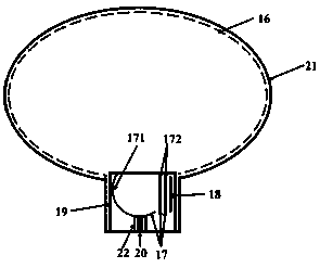
[0029] figure 1 It is a structural schematic diagram of an embodiment of a large-area photomultiplier tube with a hybrid electron multiplication system in the present invention.

[0030] like figure 1 As shown, a large-area photomultiplier tube with a hybrid electron multiplication system of the present invention mainly includes a photocathode 16, an electron multiplication system 17, an anode 18, a shielding barrel 19, and power supply and signal lead wires 20. The above-mentioned components of the photomultiplier tube of the present invention are all placed in the vacuum glass container 21, and the vacuum glass container can be spherical or ellipsoidal, and the specific shape depends on the requirements of the photoelectron transit time dispersion in t...


PUM


Abstract

The invention discloses a large-area photomultiplier with a hybrid multiplication system. The large-area photomultiplier comprises a vacuum glass container, a photocathode, the electron multiplicationsystem, an anode and a power supply electrode. The photocathode, the electron multiplication system and the anode are arranged in the vacuum glass container, the anode penetrates through the vacuum glass container through a signal lead and is connected with an external circuit, and the power supply electrode penetrates through the vacuum glass container through a power line and is connected withan external power supply circuit. The photocathode covers a whole inner surface of the vacuum glass container except a handle port. The multiplication system is arranged at an internal handle port ofthe vacuum glass container, comprises a first-stage spherical dynode and a second-stage micro-channel plate component, and can receive photoelectrons generated by the photocathode in all directions and generate multiplication electrons. The photomultiplier has advantages of a large photocathode coverage area and high photoelectron collection efficiency.

Description

technical field [0001] The invention belongs to the technical field of vacuum photodetectors, and in particular relates to a large-area photomultiplier tube with a hybrid electron multiplication system, especially to collect photoelectrons generated by a near-spherical photocathode into a structure composed of a spherical dynode and a microchannel plate. Photomultiplier tubes in hybrid electron multiplication systems. Background technique [0002] Photomultiplier tube (Photomultiplier Tube referred to as PMT) is based on the external photoelectron emission effect, secondary electron emission effect and electron optics theory. It can convert weak light signals into photoelectrons and obtain multiplication effects. There are many types of photomultiplier tubes, which can be divided into end-window type, side-window type, and newly developed large-area photomultiplier tubes according to different incident windows. Among them, large-area photomultiplier tubes have photon countin...

Claims


Application Information

Patent Timeline
Patent Type & Authority Applications(China)
IPC IPC(8): H01J43/04H01J43/10H01J43/24
CPCH01J43/04H01J43/10H01J43/246
Inventor 陈琳王兴超
Owner 深圳汇腾信息技术服务有限公司
Learn More