Covered stent

A covered stent and covering technology, which is applied to stents, blood vessels, and devices of human tubular structures, etc., can solve the problems of covering covered flanging, injury of the patient's own blood vessels, and the risk of increasing the risk of surgical difficulty and trauma, so as to ensure safe use. , Enhance the adherence, solve the effect of laminating flanging

Active Publication Date: 2020-02-25
LIFETECH SCIENTIFIC (SHENZHEN) CO LTD
View PDF11 Cites 4 Cited by
  • Summary
  • Abstract
  • Description
  • Claims
  • Application Information

AI Technical Summary

Problems solved by technology

After the stent is implanted, if the metal stent shifts or warps, not only the shape of the stent and the therapeutic effect are not good, but also type I endoleak is likely to occur, and a second intervention is required to ensure the therapeutic effect of the operation, which increases the cost of surgical treatment. time, increasing the difficulty of the operation and the risk of intraoperative trauma to the patient
In addition, the displacement of the metal stent and the tilting of the metal stent can easily cause damage to the patient's own blood vessels
[0005] Based on this, it is necessary to provide a stent graft with good wall-adherence, which can solve the problem of the flanging of the stent graft, so that type I endoleak is not easy to occur after the stent is implanted in the human body.

Method used


Image

  • Covered stent
  • Covered stent
  • Covered stent

Examples


Embodiment 1

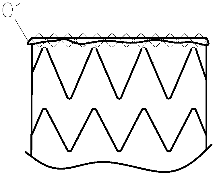
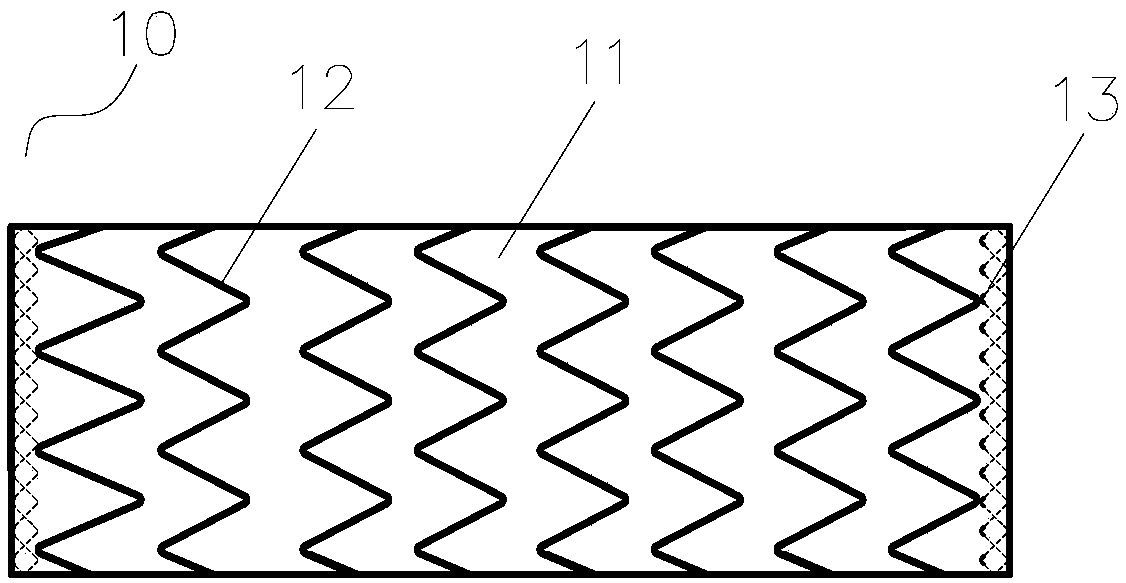
[0031] Such as image 3 As shown, the stent graft 10 of this embodiment is a hollow elongated columnar structure with openings at both ends, including a tubular stent 11, a plurality of main body stent units 12 arranged at intervals along the length direction of the stent 11, and respectively arranged on the stents. 11 two first bracket units 13 at the proximal end and the distal end. Wherein, the main support unit 12 is arranged on the outer side of the covering film 11 , and the first supporting unit 13 is arranged on the inner side of the covering film 11 . Both the main frame unit 12 and the first bracket unit 13 are connected to the membrane 11 through sutures, which can be made of biocompatible materials, such as PET sutures or PTFE sutures. The membrane 11 can be an artificial blood vessel, or a tubular polyester cloth, or other conventional membrane materials used to manufacture stent grafts.

[0032] The main frame unit 12 is roughly in the shape of a repeated W, ma...

Embodiment 2

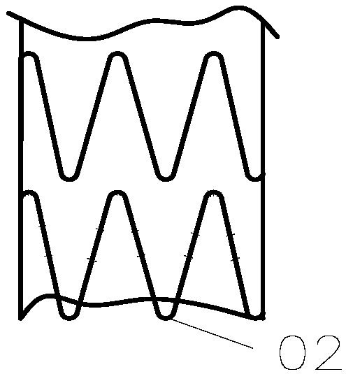
[0043] Such as Figure 7 As shown, the structure of the stent-graft 20 of this embodiment is substantially the same as that of the stent-graft 10 of the first embodiment, except that the proximal end of the stent-graft 20 of this embodiment is provided with a plurality of first stent units connected to each other. twenty three. Such as Figure 8 As shown, the crest of the farthest first support unit 23a is connected to the trough of the adjacent first support unit 23b, and the crest of the first support unit 23b is connected to the trough of another first support unit adjacent thereto, A plurality of first bracket units are combined together through the peak-to-trough interconnection. The number of first stent units sutured with the membrane 21 is preferably no more than 3, too many will lead to insufficient support at the proximal end of the membrane stent 20, and the membrane stent 20 of this embodiment only has the most distal first bracket unit 23a is sewn on the cover ...


PUM


Abstract

The invention provides a covered stent, which comprises a tubular covered membrane and at least one first stent unit connected with the end of the covered membrane, each first stent unit comprises first wave rings and second wave rings, and the first wave rings and the second wave rings are overlapped to form a plurality of intersection points; wherein each of the first wave ring and the second wave ring comprises a plurality of wave crests and a plurality of wave troughs, at least one sewing knot is arranged at at least one of the adjacent wave crests and wave troughs, and at least one sewingknot is arranged at the intersection point. According to the covered stent, the first stent unit is tightly sewn with the covered membrane, so that the adherence of the stent and the sealing performance of the covered stent are greatly enhanced, the problem of covered membrane flanging of the covered stent is solved, the use safety of the implanted stent is guaranteed, and I-type inner leakage isavoided.

Description

technical field [0001] The invention relates to the field of implanted medical devices, in particular to a covered stent. Background technique [0002] Aortic aneurysm and aortic dissection are extremely dangerous diseases, mainly divided into aortic dissection, aortic true aneurysm, and aortic pseudoaneurysm. The mortality rate of aortic disease is greater than 50% 48 hours after the onset, and greater than 5% 2 weeks after the onset, which has seriously threatened human health. With the arrival of the aging trend in China, the incidence of aortic aneurysm and aortic dissection will continue to rise. [0003] For aortic disease, the main treatment at present is artificial vascular graft. Therefore, a large number of artificial vascular stents are clinically required as vascular substitutes. At present, stents made of polyester (PET), polytetrafluoroethylene (PTFE), natural silk and other artificial materials have been used clinically, and satisfactory results have been a...

Claims


Application Information

Patent Timeline
Patent Type & Authority Applications(China)
IPC IPC(8): A61F2/07
CPCA61F2/07A61F2/06
Inventor 肖本好黄新鑫
Owner LIFETECH SCIENTIFIC (SHENZHEN) CO LTD
Why Eureka
Try Eureka