
Motor accelerated lifetime test method and system

A technology of accelerated life test and motor speed, which is used in engine testing, machine/structural component testing, measuring devices, etc. It can solve the problems of low accuracy of motor accelerated life test time, shorten the test time and improve reliability. , to ensure the effect of normal operation

Active Publication Date: 2020-02-25
ZHENGZHOU YUTONG BUS CO LTD
View PDF7 Cites 14 Cited by
  • Summary
  • Abstract
  • Description
  • Claims
  • Application Information

AI Technical Summary

Problems solved by technology

[0005] The object of the present invention is to provide a motor accelerated life test method and system, which is used to solve the problem of low accuracy of the motor accelerated life test time in the prior art

Method used


Image

  • Motor accelerated lifetime test method and system
  • Motor accelerated lifetime test method and system
  • Motor accelerated lifetime test method and system

Examples


Embodiment 1

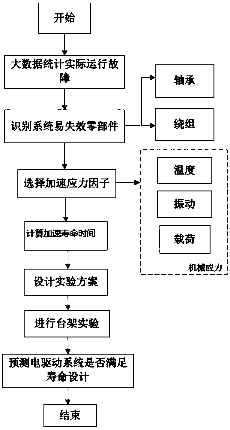
[0045] like figure 1 As shown, firstly, the failure modes and failure mechanisms that are prone to occur in the motor during the actual operation of the vehicle are counted through big data, the parts that are prone to failure in the system are identified, and the main factors causing failure are further analyzed, including environmental factors, electrical and mechanical stress factors, etc. For the motor bearings and windings of the weak parts obtained in the previous analysis, the statistical analysis theory of the failure compliance of the weak parts is analyzed separately, and then the acceleration factor is calculated for the failure rate compliance of the weak parts, according to the reliability, confidence and life requirements. Determine the final accelerated life test time, design the test method, and conduct the test on the bench to predict whether the motor system meets the design life.

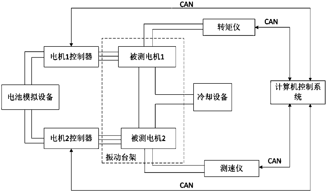
[0046] like figure 2 As shown, the life of the motor system is predicted th...

Embodiment 2

[0063] In this embodiment, the temperature of the winding is also selected as the acceleration stress. First, the total test time of the winding is determined according to the number of samples, reliability and confidence through statistical rules, and then the acceleration factor of the winding is determined according to the actual operating condition of the winding, and finally the acceleration of the winding is determined. Life test time, design an accelerated life test bench, real-time monitoring of test failures, and finally determine whether the life of this batch of motors meets the design life through the test results.

[0064] The determination of the accelerated life time of the winding in this embodiment includes the following steps:

[0065] 1) The calculation process of the conventional life test time of the motor winding is as follows:

[0066] The failure of the motor windings satisfies the exponential distribution, and its failure rate λ c As shown in formula ...


PUM


Abstract

The invention provides a motor accelerated lifetime test method and system. The motor accelerated lifetime test method comprises the steps of firstly, selecting a bearing as a factor of affecting motor lifetime, and calculating conventional lifetime test time of the bearing; secondly, calculating a factor acceleration factor according to an equivalent dynamic load borne by the bearing, a motor rotational speed and acceleration power spectrum density; thirdly, calculating accelerated lifetime test time of the bearing; and finally, loading a parameter required by motor test, applying vibration load spectrum, allowing a to-be-measured motor to continuously run within the accelerated lifetime test time for accelerated lifetime test, and judging whether the to-be-measured motor is in failure ornot. By the motor accelerated lifetime test method, a vibration factor generated during the vehicle running process is considered, so that the accelerated lifetime test is more approximate to a realcondition, and the motor lifetime test time can be reduced; and the motor lifetime can be accurately obtained, a relevant person is convenient to timely acquire the motor lifetime, a new motor is replaced in advance when the motor lifetime is almost ended, so that normal running of the whole running is ensured.

Description

technical field [0001] The invention belongs to the technical field of new energy motors, and particularly relates to a motor accelerated life test method and system. Background technique [0002] New energy vehicles have the advantages of energy saving and environmental protection, and have become an emerging field in recent years. As one of the three electric drives, electric drive systems have also developed. Traditional motors are mostly used in home appliances, power tools, wind and hydropower and other fields. Passenger cars and commercial vehicles are very different. In order to ensure the safe and reliable application of motors in the automotive field, it is necessary to study the reliability of motors under vehicle driving conditions. [0003] The design life of the motor drive system reaches hundreds of thousands of kilometers, and its life test assessment is difficult. There is no special equipment for the life test of the vehicle motor drive system. There are two...

Claims


Application Information

Patent Timeline
IPC IPC(8): G01M15/00
CPCG01M15/00
Inventor 王丹迎纪秉男韩守亮康娟张振宁韩光辉秦亚坤
Owner ZHENGZHOU YUTONG BUS CO LTD
Learn More