Hyperspectral system for gas concentration detection

A gas concentration detection and hyperspectral technology, applied in the field of hyperspectral systems, can solve problems such as spectral line bending, spectral accuracy and luminous flux limitation, and reduce system spectral sensitivity, so as to improve concentration detection limit, hyperspectral resolution, and improve The effect of number of species

Pending Publication Date: 2020-02-28
苏州铭坤科技有限公司
View PDF0 Cites 1 Cited by
  • Summary
  • Abstract
  • Description
  • Claims
  • Application Information

AI Technical Summary

Problems solved by technology

[0007] 1. In order to use a fiber optic spectrometer, the light input aperture of the absorption cavity is very small, which limits the light flux of the system, thereby affecting the detection limit of the gas concentration
[0008] 2. The output aperture of the absorption cavity is also very small, the outgoing light is guided by the optical fiber, and the luminous flux is limited by the aperture of the optical fiber; the luminous flux and light energy utilization rate are low; to a certain extent, the spectral sensitivity of the system is reduced
[0009] 3. The grating dispersion spectroscopic principle of the fiber optic spectrometer determines that it inevitably has the disadvantage of spectral line bending, and uses a slit whose width is inversely proportional to the spectral resolution in the spectrometer, so its spectral accuracy and luminous flux are limited
[0010] 4. The spectral resolution of the entire optical fiber spectroscopy system is low (up to about 1nm), which limits the types of detectable gases and the concentration detection limit

Method used


Image

  • Hyperspectral system for gas concentration detection

Examples


Embodiment Construction

[0018] In order to make the purpose, content, and advantages of the present invention clearer, the specific implementation manners of the present invention will be further described in detail below in conjunction with the accompanying drawings and embodiments.

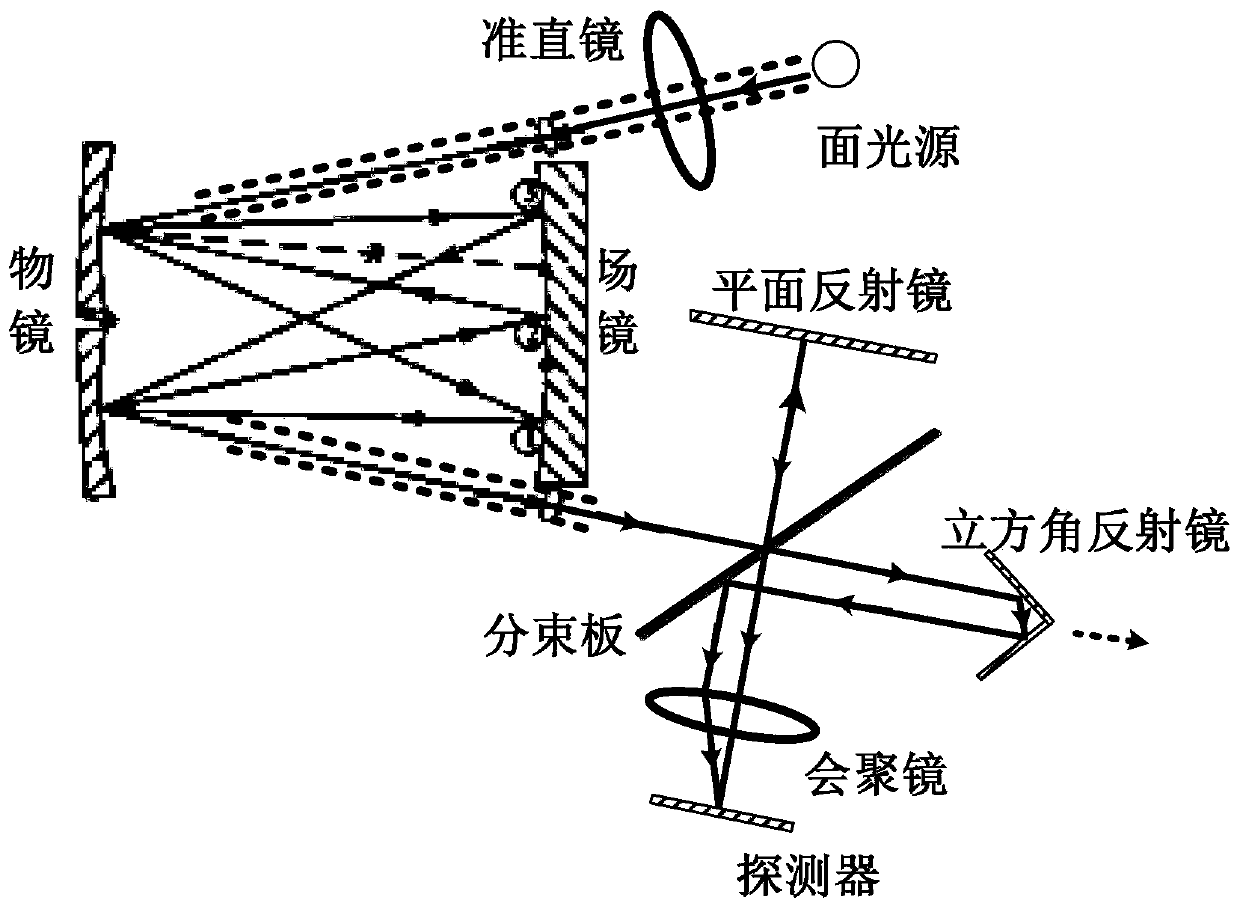
[0019] This patent proposes a spectroscopic system for gas concentration detection, which uses a multi-path optical absorption cavity to increase the optical path of light in the gas to be measured, improve the signal-to-noise ratio, and improve the detection limit and detection accuracy of gas concentration; the system The spectrum acquisition system of our company adopts a double optical path interference device to obtain the interference signal of the target gas. The mirror of one path can be moved to produce a series of changing optical path differences, and the absorption spectrum of the target gas is obtained by Fourier transform.

[0020] The invention organically combines the optical absorption cavity and the hy...


PUM

PropertyMeasurementUnit
angleaaaaaaaaaa

Abstract

The invention discloses a hyperspectral system for gas concentration detection. Light emitted by a light source is collimated by a collimating mirror to form parallel light with a set numerical aperture, and the parallel light enters a objective lens of an optical absorption cavity, and is folded back for multiple times between the objective lens and a field lens of the optical absorption cavity;the light absorbed by gas in the optical absorption cavity enters a beam splitting plate of a double-light-path interference structure through repeated fold-back, and the light entering the beam splitting plate is divided into two paths according to the ratio of 1: 1, wherein one path is reflected to a plane mirror through the beam splitting plate, reflected to the beam splitting plate through theplane mirror and transmitted to a convergent mirror through the beam splitting plate, and the other path is transmitted to a cubic corner reflector through the beam splitting plate, reflected to thebeam splitting plate through the cubic corner reflector, and finally reflected to the convergent mirror through the beam splitting plate; and a convergent mirror converges the two paths of light and images the light to a detector. The system has the advantages of high spectral resolution and high flux, high-resolution spectral data with a high signal-to-noise ratio can be obtained, and finally theconcentration detection limit of a detection system is improved.

Description

technical field [0001] The invention belongs to the technical field of photoelectric detection and relates to a hyperspectral system for gas concentration detection. Background technique [0002] Optical absorption spectroscopy is a gas concentration detection method, and gas spectrum acquisition is the basis and key technology for concentration inversion by optical absorption spectroscopy. The resolution of gas absorption spectrum determines the number of detectable gases and the detection limit. . [0003] At present, the traditional absorption spectroscopy method to detect gas concentration mostly uses an optical absorption cavity to increase the light path of the gas. By increasing the light path in the gas, the ability to detect low-concentration gases is improved (the detection limit is increased). At the output aperture of the absorption cavity, a fiber optic spectrometer is used to obtain the characteristic absorption spectrum of the target gas, and then the optical...

Claims


Application Information

Patent Timeline
Patent Type & Authority Applications(China)
IPC IPC(8): G01N21/31G01N21/03
CPCG01N21/0303G01N21/31
Inventor 廉玉生刘子龙
Owner 苏州铭坤科技有限公司
Why Eureka
Try Eureka