Photoetching machine control system and method

A technology of control system and lithography machine, which is applied in the field of lithography machines, can solve the problems of unable to meet the data transmission requirements of high-end lithography machines, the increase of data transmission bandwidth, and the sensor’s susceptibility to electromagnetic interference, etc., so as to avoid complex Effects of program design, increased bandwidth, increased reliability and transfer speed

Inactive Publication Date: 2020-03-10
SHANGHAI MICRO ELECTRONICS EQUIP (GRP) CO LTD
View PDF5 Cites 2 Cited by
  • Summary
  • Abstract
  • Description
  • Claims
  • Application Information

AI Technical Summary

Problems solved by technology

However, with the continuous improvement of the servo frequency of the motion table motor of the lithography machine and the processing and collection of more and more high-speed real-time data, the traditional control hardware system of the lithography machine based on the VME parallel bus has been unable to meet its requirements. Increased demand for data transmission bandwidth
Although the VME64x with the largest bandwidth so far has reached 320Mbps (Byte / s), it still cannot meet the data transmission requirements of high-end lithography machines
In addition, in the control system of the lithography machine, there are a large number of weak signal sensors, such as: capacitive sensors, eddy current sensors, light energy sensors, etc. If the data transmission method is not selected correctly, these sensors are extremely susceptible to electromagnetic interference, and then Affecting the performance indicators of the lithography machine

Method used


Image

  • Photoetching machine control system and method
  • Photoetching machine control system and method
  • Photoetching machine control system and method

Examples


Embodiment 1

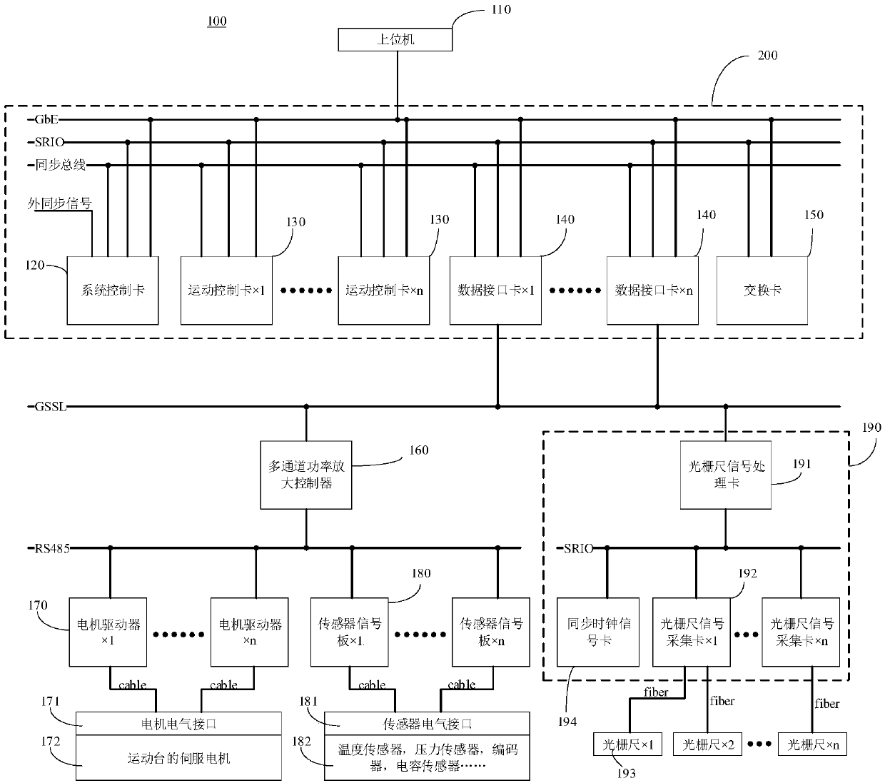
[0045] Please refer to figure 1 , Embodiment 1 of the present invention provides a lithography machine control system 100, including a host computer 110 system control card 120, a motion control card 130, a data interface card 140, an exchange card 150, a multi-channel power amplifier controller 160, and a motor driver 170 , a sensor signal board 180 and a position measurement unit 190 .

[0046] Among them, the system control card 120, the motion control card 130, the data interface card 140 and the switch card 150 are connected through the VPX bus (SRIO) for data transmission.

[0047] Wherein, the system control card 120 , the motion control card 130 , the data interface card 140 and the switch card 150 are connected to the host computer 110 through Ethernet (GbE) for command processing.

[0048] Wherein, the system control card 120, the motion control card 130 and the data interface card 140 are connected with a synchronization bus, which is used to synchronize the clock ...

Embodiment 2

[0098] Please refer to Figure 6 , the lithography machine control system provided in the second embodiment of the present invention is improved on the basis of the first embodiment, the difference lies in the connection mode of the sensor signal board 180 . That is, the input end of the sensor signal board 180 in Embodiment 2 of the present invention is connected to various sensors, and the output end of the sensor signal board 180 is directly connected to the data interface card 140 through an optical fiber or other wires; that is, the sensor signal board 180 can be It is directly connected to the data interface card 140 through the optical fiber interface instead of the power amplification controller 160 . The sensor signal board 180 directly sends the underlying sensor data to the data interface card 140 through the GSSL protocol, and the data interface card 140 parses the data format of the GSSL protocol into the data format of the SRIO protocol, and then forwards it to t...

Embodiment 3

[0102] Please refer to Figure 7 , the lithography machine control system provided in the third embodiment of the present invention is improved on the basis of the first embodiment, the difference lies in the connection mode of the sensor signal board 180 . In Embodiment 3 of the present invention, the input end of the sensor signal board 180 is connected to the sensor, and the output end of the sensor signal board 180 is connected to the motion control card 130 by optical fibers or other wires through a channel of the multi-channel power amplifier controller 160 . That is, in the third embodiment of the present invention, on the basis of the first embodiment, the data interface card 140 is removed, and the power amplifier controller 160 and the motion control card 130 are directly connected through an optical fiber. Compared with Embodiment 1 and Embodiment 2, this embodiment omits the data interface card 140 , but uses the optical fiber interface of the motion control card 1...


PUM


Abstract

The invention provides a photoetching machine control system and method. The control system comprises a system control card, a motion control card, a data interface card, an exchange card, a multi-channel power amplification controller, a motor driver, a sensor signal board, a position measurement unit and an upper computer. According to the invention, the motion precision and speed of a motion platform motor can be improved, and electromagnetic interference is reduced.

Description

technical field [0001] The invention relates to the field of lithography machines, in particular to a control system and method for a lithography machine. Background technique [0002] The lithography machine control system is the "brain" and "nerve" of the lithography machine. It can organically connect all sub-systems and make them work in an orderly manner. Through the whole machine management software of the lithography machine, the program can be set and coordinated to realize the control of various functions of the lithography machine and complete the control of the lithography machine. individual workflows. The control hardware architecture aims to provide a reliable and compatible control platform for each subsystem, and constrain the control implementation of each subsystem, and finally meet the performance index requirements of the product. However, with the continuous improvement of the servo frequency of the motion table motor of the lithography machine and the...

Claims


Application Information

Patent Timeline
IPC IPC(8): G03F7/20
CPCG03F7/70491G03F7/70525
Inventor 王伟李蒙
Owner SHANGHAI MICRO ELECTRONICS EQUIP (GRP) CO LTD
Why Eureka
Try Eureka